Ahmedabad
+919157924641

'prevent web breaks'

Items tagged with 'prevent web breaks'

product image
Force Transducer

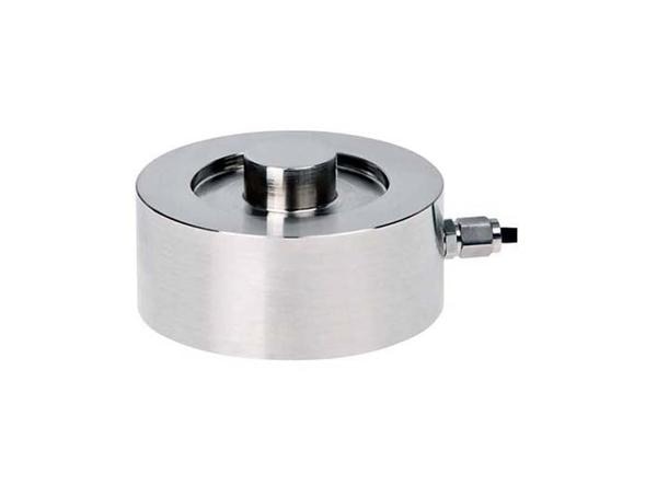
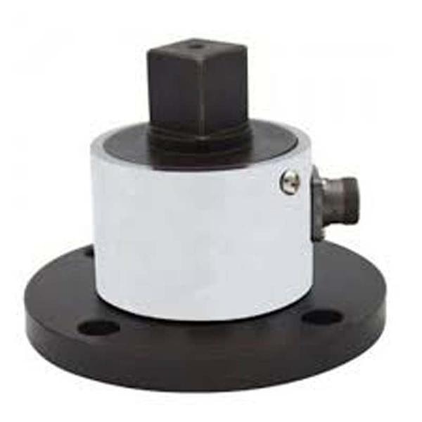
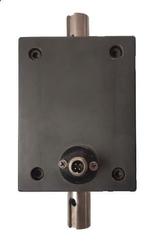
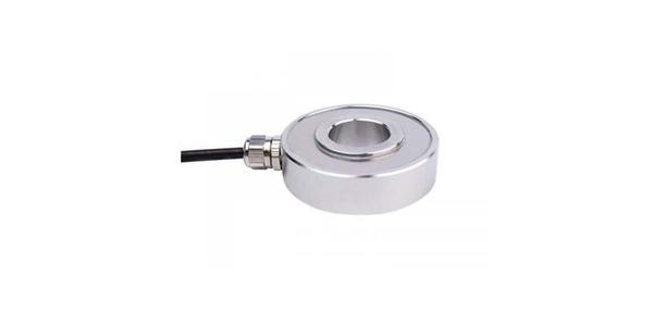
Master Your Production with Precision: The Definitive Guide to Web Tension Load Cells In the fast-paced world of modern manufacturing, where precision, efficiency, and quality are paramount, subtle yet critical factors can make or break a production line. Among these, web tension control stands out as a fundamental requirement across diverse industries. From delicate films to robust textiles, maintaining optimal tension is the secret ingredient for flawless end products, reduced waste, and maximized throughput. At the heart of this crucial process lies the web tension load cell – a highly specialized sensor designed to accurately measure and control the pulling force on continuous materials. This comprehensive guide will delve deep into the world of web tension load cells, exploring their working principles, diverse applications, undeniable benefits, types, and essential considerations for selection, installation, and calibration. Whether you're a manufacturer in the printing, packaging, textile, or converting industry, understanding and leveraging the power of web tension load cells is key to unlocking superior performance and profitability. What is a Web Tension Load Cell and How Does It Work? A web tension load cell is a sophisticated force sensor specifically engineered to measure the tension or pulling force applied to a continuous sheet or web of material as it moves through a processing line. Unlike conventional load cells designed for general weighing or compression, web tension load cells are optimized for precise detection of relatively low forces in dynamic web handling environments. The core principle behind most web tension load cells is the strain gauge technology. Here's a simplified breakdown of how they operate: Sensing Beam/Element: The load cell incorporates a meticulously designed sensing element, often a bending beam or a differential bending beam, which is strategically positioned to come into contact with the web or roller supporting the web. Strain Gauges: Tiny electrical resistors called strain gauges are precisely bonded to this sensing element. These gauges are highly sensitive to minute deformations. Force to Deformation: As the web exerts tension on the roller, the sensing element within the load cell experiences a slight deformation or strain. Resistance Change: This deformation causes the strain gauges to stretch or compress, leading to a proportional change in their electrical resistance. Electrical Signal: These changes in resistance are then converted into a measurable electrical signal (typically a voltage change) by a Wheatstone bridge circuit. Signal Processing: The electrical signal, often in millivolts (mV), is then amplified by a load cell amplifier and transmitted to a tension controller. Real-time Feedback & Control: The tension controller processes this signal, compares it to a pre-set tension target, and then sends corrective signals to actuators like brakes, motors, or clutches. This creates a closed-loop control system, continuously adjusting the tension to maintain the desired level. This real-time feedback loop is crucial for preventing material defects, optimizing machine speed, and ensuring consistent product quality. Why Are Web Tension Load Cells Indispensable? The Benefits Unleashed The precise control offered by web tension load cells translates into a multitude of significant benefits for manufacturers: Superior Product Quality: This is arguably the most critical advantage. Consistent web tension prevents a host of defects such as wrinkling, creasing, stretching, tearing, misregistration in printing, and uneven coating. This leads to a higher quality end product that meets stringent specifications and reduces customer complaints. Reduced Material Waste: By preventing material damage and ensuring optimal processing, web tension load cells drastically cut down on scrap and rework, leading to substantial cost savings. Increased Production Efficiency and Throughput: With stable tension, machines can operate at higher speeds without fear of web breaks or material handling issues. This maximizes production capacity and reduces downtime. Enhanced Machine Uptime and Longevity: By preventing excessive stress on machinery components due to uncontrolled tension, load cells contribute to smoother operation, reduced wear and tear, and extended lifespan of equipment. Optimized Process Control: Real-time feedback allows for dynamic adjustments, adapting to changes in material properties, machine speed, or environmental conditions, ensuring consistent performance throughout the production run. Greater Automation Compatibility: Web tension load cells seamlessly integrate with modern PLC and SCADA systems, enabling fully automated tension control, minimizing manual intervention, and freeing up operators for other critical tasks. Data Logging and Analysis: Many advanced load cell systems offer data logging capabilities, providing valuable insights into tension profiles over time. This data can be used for process optimization, troubleshooting, and predictive maintenance. Improved Safety: By preventing web breaks and sudden tension fluctuations, load cells contribute to a safer working environment for operators. Diverse Applications Across Industries Web tension load cells are the unsung heroes in a wide array of industries that handle continuous web materials: Printing Industry: Critical for maintaining consistent registration, preventing paper breaks, and ensuring high-quality print on paper, film, and foil in flexographic, offset, digital, and gravure printing presses. Packaging Industry: Essential for controlling tension in films, foils, and laminates during processes like laminating, slitting, rewinding, form-fill-seal operations, and label manufacturing. Textile Industry: Used in weaving, knitting, coating, and finishing processes to maintain even yarn and fabric tension, preventing irregularities, snags, and ensuring consistent fabric quality. Converting Industry: Broadly encompasses various processes like slitting, rewinding, coating, laminating, and embossing of paper, plastic films, non-wovens, and metal foils. Plastic Film Extrusion: Crucial for controlling tension in blown film and cast film lines to ensure uniform thickness and consistent material properties. Wire and Cable Manufacturing: Employed to monitor and control tension during wire drawing, stranding, and winding operations, preventing breakage and ensuring product integrity. Tyre Manufacturing: Used in various stages involving rubber sheeting and cord winding to maintain precise tension. Battery Production: Involves coating and slitting processes where consistent tension of electrode materials is vital for battery performance. Types of Web Tension Load Cells While the underlying principle of strain gauge technology remains common, web tension load cells come in various forms to suit different installation requirements and applications: Pillow Block Load Cells: These are commonly integrated directly into the machine frame, often replacing or complementing existing pillow block bearings. They measure the horizontal and/or vertical forces exerted by the roller shaft. Flange Mounted Load Cells: Designed for easy installation, these load cells are typically mounted to a machine frame with a flange, providing a direct measurement point for web tension. Cantilever Load Cells: Often used in applications with single-sided web support, these compact load cells are ideal for measuring tension in narrow webs or on cantilevered rollers. Through-Shaft Load Cells: These load cells are designed to fit directly onto the shaft of the roller, offering a compact and direct measurement solution. Sensor Rollers: These are specialized rollers with integrated load cell technology, offering a self-contained and often simpler installation for tension measurement. Flat Load Cells: Compact and low-profile designs that fit into tight spaces, measuring tension across a flat surface. Round/Axial Load Cells: Designed for specific mounting configurations, often to measure tension along an axial direction. The choice of load cell type depends on factors like available space, roller configuration, web width, tension range, and environmental conditions. Selection, Installation, and Calibration: Key Considerations To maximize the performance and lifespan of your web tension load cells, consider these vital aspects: Selection: Tension Range: Crucial to match the load cell's capacity to the expected tension range of your application. Overloading can damage the sensor, while an undersized sensor may lack sensitivity. Accuracy and Sensitivity: High precision is key for optimal control. Look for specifications like non-linearity, hysteresis, and repeatability. Environmental Factors: Consider operating temperature, humidity, dust, and potential for corrosive elements. Choose load cells with appropriate IP ratings and material construction (e.g., stainless steel for harsh environments). Mounting Configuration: Ensure the load cell type is compatible with your machine's design and roller setup. Output Signal: Most load cells provide a mV/V output, which needs to be compatible with your tension controller. Overload Protection: Important for safeguarding the load cell from accidental damage due to sudden force spikes. Installation: Proper Alignment: Incorrect alignment is a common cause of inaccurate readings. Ensure the load cell is perfectly aligned with the direction of the web tension. Rigid Mounting: The mounting surface must be stable and rigid to prevent extraneous forces from affecting measurements. Cable Routing: Protect sensor cables from mechanical damage, electrical interference (EMC), and extreme temperatures. Use shielded cables where necessary. Manufacturer Guidelines: Always strictly follow the manufacturer's installation instructions for optimal performance and longevity. Calibration: Regular Calibration: Load cells, like any precision instrument, require periodic calibration to maintain accuracy and compensate for potential drift over time. Zeroing: Before applying any tension, the load cell system must be “zeroed” to account for any residual load or tare weight. Multi-point Calibration: For optimal accuracy, perform calibration at multiple points across the expected tension range using certified calibration weights or known forces. Professional Calibration: For critical applications, consider engaging professional calibration services to ensure compliance with industry standards. Documentation: Maintain detailed records of all calibration activities for traceability and quality assurance. The Future of Web Tension Control As industries move towards even greater automation and intelligent manufacturing, web tension load cells will continue to evolve. Advancements include: Enhanced Connectivity: Integration with Industrial IoT (IIoT) platforms for remote monitoring, predictive maintenance, and data analytics. Miniaturization: Smaller, more compact designs for integration into increasingly complex and space-constrained machinery. Advanced Materials: Development of new materials for improved durability, temperature stability, and higher overload capacities. AI and Machine Learning Integration: Leveraging AI for predictive tension control, anomaly detection, and self-optimization of web handling processes. Partnering for Precision Choosing the right web tension load cell and implementing an effective tension control system is a crucial investment for any manufacturer aiming for superior product quality and operational excellence. By understanding the principles, benefits, and considerations outlined in this guide, you can make informed decisions that drive efficiency, reduce waste, and ultimately, elevate your production capabilities. Partner with reputable manufacturers and suppliers who can provide not only high-quality web tension load cells but also expert advice, technical support, and comprehensive after-sales service. Your journey towards mastering web tension control starts here. We are also supply in Andhra Pradesh, Arunachal Pradesh, Assam, Bihar, Chhattisgarh, Goa, Gujarat, Haryana, Himachal Pradesh, Jharkhand, Karnataka, Kerala, Madhya Pradesh, Maharashtra, Manipur, Meghalaya, Mizoram, Nagaland, Odisha, Punjab, Rajasthan, Sikkim, Tamil Nadu, Telangana, Tripura, Uttar Pradesh, Uttarakhand, and West Bengal

Send Message
product image
SINGLE POINT LOAD CELL

Introduction Load cells are fundamental components in a vast array of weighing and force measurement systems, converting mechanical force into an electrical signal. While conventional load cells are designed to measure force applied along a specific axis, often at a single, central point, many real-world applications involve loads that are not perfectly centered. This challenge led to the development of off-center load cells, also commonly known as single point load cells. These specialized sensors are engineered to accurately measure a load regardless of its position on a weighing platform, within specified limits. Their unique design and internal compensation mechanisms make them indispensable for applications ranging from retail scales to industrial platforms, where the precise placement of an object cannot always be guaranteed. Basic Principle of Load Cells Before delving into off-center load cells, it's crucial to understand the fundamental working principle of a load cell. Most load cells operate on the principle of strain gauges. A strain gauge is a small, foil-based sensor whose electrical resistance changes proportionally when it is stretched or compressed (strained). A typical load cell body, often made of aluminum, steel, or stainless steel, is precisely machined to create a “flexure” or “spring element.” When a force is applied, this flexure deforms elastically. Strain gauges are strategically bonded to the surface of this flexure at points where the deformation (strain) is maximized. These strain gauges are then wired into a Wheatstone bridge circuit. A Wheatstone bridge is an electrical circuit used to measure an unknown electrical resistance by balancing two legs of a bridge circuit, one leg of which includes the unknown component. In a load cell, as the strain gauges deform, their resistance changes, unbalancing the bridge. This imbalance generates a small voltage output that is directly proportional to the applied force. This voltage signal is then amplified, digitized, and processed by an indicator or control system to display the weight or force. The Challenge of Off-Center Loading In many weighing applications, especially those involving platforms, the load is rarely applied perfectly at the center. Imagine a retail scale where a customer places an item anywhere on the pan, or an industrial platform scale where a pallet might be pushed to one side. If a standard, single-beam load cell were used in such a scenario, applying the load away from its central axis would introduce bending moments and shear forces that are not uniformly distributed across the strain gauges. This non-uniform stress distribution would lead to inaccurate readings, as the bridge output would vary depending on where the load was placed, even if the total weight remained constant. This phenomenon is known as “corner error” or “eccentric load error.” To overcome this, traditional multi-load cell systems would be required, using four or more standard load cells, one at each corner of the platform. While effective, this approach increases complexity, cost, and the number of components that can fail or go out of calibration. Design and Construction of Off-Center Load Cells Off-center load cells, primarily characterized by their “single point” design, are specifically engineered to counteract eccentric loading effects. They are typically block-shaped, often made from aluminum (for lower capacities) or stainless steel (for higher capacities and harsh environments). The key to their off-center compensation lies in: Rigid Body Design: Unlike simple bending beams, off-center load cells feature a more complex, often parallel-beam or shear-beam construction. The top and bottom surfaces are designed to remain parallel even under load, ensuring that the force is transmitted uniformly to the internal sensing elements. Multiple Strain Gauges and Strategic Placement: Instead of just two or four strain gauges, off-center load cells typically incorporate four or more active strain gauges. These gauges are precisely positioned on the internal flexure elements in such a way that any eccentric load causes a combination of tension and compression in different gauges. Internal Compensation: The genius of the off-center load cell lies in how these multiple strain gauges are wired into the Wheatstone bridge circuit. They are configured in a way that the effects of an off-center load on one set of gauges are precisely counteracted by the effects on another set. For example, if a load applied to one side causes a certain strain, the design ensures that a corresponding, opposite strain is induced in another part of the flexure, and the gauges sensing these strains are wired to cancel out the eccentric effect on the overall bridge output. This results in a net output that is solely proportional to the vertical component of the applied force, regardless of its horizontal position on the platform. The manufacturing process for these load cells is highly precise, involving advanced machining techniques to create the complex internal flexures and meticulous bonding of the strain gauges. This precision is critical to achieving the specified accuracy and off-center load compensation. How Off-Center Load Cells Compensate The compensation mechanism relies on a sophisticated arrangement of strain gauges within the Wheatstone bridge. Consider a common single point load cell design: Four Active Gauges: Typically, four active strain gauges are used. These are positioned on the internal web or shear elements of the load cell. Bridge Configuration: The gauges are wired into a full Wheatstone bridge. When a load is applied centrally, all gauges experience a predictable strain, leading to a proportional output. Eccentric Load Effect: When an eccentric load is applied (e.g., towards one end of the load cell's platform), it introduces a bending moment in addition to the vertical force. This bending moment would normally cause uneven strain across the gauges. Self-Correction: The unique placement and wiring ensure that the strains caused by the bending moment are effectively “cancelled out” within the bridge. For instance, if the eccentric load causes one gauge to experience increased tension and another to experience increased compression due to the bending, the bridge is wired so that these opposing effects negate each other in the final output signal. The only remaining, uncancelled effect is that due to the pure vertical force, leading to an accurate reading irrespective of load position. This internal compensation allows a single off-center load cell to support a relatively large weighing platform (often up to 600x600mm or more, depending on the load cell's capacity and design) and provide accurate readings across its entire surface. Advantages of Off-Center Load Cells The distinct design of off-center load cells offers several significant advantages: Accuracy with Eccentric Loads: This is their primary benefit. They provide highly accurate measurements even when the load is not centrally placed on the weighing platform, minimizing “corner error.” Simplified Mechanical Design: For platform scales, only a single off-center load cell is required, eliminating the need for complex mechanical linkages or multiple standard load cells. This simplifies the scale's construction, reduces material costs, and makes assembly easier. Cost-Effectiveness: While a single off-center load cell might be more expensive than a single standard load cell, it is often more cost-effective than a system requiring four or more standard load cells, along with summing boxes and mounting hardware. Reduced Footprint: The ability to use a single load cell allows for more compact and streamlined scale designs, which is crucial in applications with limited space. Easier Calibration and Maintenance: With only one load cell, calibration procedures are simplified, and troubleshooting potential issues becomes less complex. Applications Off-center load cells are widely used across various industries due to their versatility and accuracy in handling eccentric loads: Platform Scales: This is their most common application, including retail scales (checkout scales), postal scales, bench scales, and small to medium-sized industrial platform scales. Weighing Hoppers and Tanks: Used in process control to measure the contents of hoppers, tanks, and silos, where the material might settle unevenly. Packaging Machinery: Integrated into automated packaging lines to accurately weigh products as they are filled or packaged. Conveyor Belt Weighing: While often using specialized designs, the principle of compensating for distributed or uneven loads is similar. Medical Devices: Found in patient weighing scales, laboratory balances, and other medical equipment requiring precise and reliable weight measurement. Checkweighers: Essential for high-speed checkweighing applications where products move rapidly across a platform and need to be weighed accurately on the fly. Key Considerations for Selection and Installation When selecting and installing off-center load cells, several factors must be considered to ensure optimal performance: Capacity: Choose a load cell with a capacity that comfortably exceeds the maximum expected load, including any tare weight. Overloading can cause permanent damage. Accuracy Class: Load cells are classified by their accuracy (e.g., OIML R60 classes). Select a class appropriate for the required precision of the application. Platform Size: The maximum recommended platform size for a given off-center load cell is crucial. Exceeding this size can compromise off-center compensation. Material and Environmental Factors: Consider the operating environment. Stainless steel load cells with high IP ratings (Ingress Protection) are suitable for harsh, wet, or corrosive conditions. Aluminum is often used for dry, indoor applications. Mounting: Proper mounting is critical. The load cell must be installed on a rigid, level surface, and the platform should be securely attached without introducing any binding or side forces. Anti-lift-off devices or overload protection may be necessary. Calibration: Regular calibration with certified test weights is essential to maintain accuracy over time. Cable Length and Shielding: Ensure the cable length is adequate and that it is properly shielded to prevent electromagnetic interference (EMI) from affecting the signal. Maintenance and Troubleshooting Like any precision instrument, off-center load cells require proper maintenance and occasional troubleshooting: Regular Checks: Periodically inspect the load cell and its mounting for any signs of damage, corrosion, or loose connections. Cleanliness: Keep the area around the load cell clean, especially preventing debris from accumulating between the load cell and the platform, which can cause binding. Overload Protection: Ensure that any overload protection mechanisms are functioning correctly to prevent damage from excessive loads. Moisture Ingress: For load cells in wet environments, regularly check the integrity of cable glands and seals to prevent moisture ingress, which can lead to signal drift or failure. Troubleshooting: Common issues include unstable readings (often due to vibration, binding, or EMI), zero drift (temperature changes, creep, or mechanical issues), and inaccurate readings (calibration issues, overload, or damage). A multimeter can be used to check bridge resistance and output voltage for basic diagnostics. Conclusion Off-center load cells are a testament to innovative engineering in the field of force measurement. By cleverly compensating for eccentric loading, they have revolutionized the design and functionality of weighing platforms, making accurate and reliable measurements possible in diverse real-world scenarios where perfect load placement is impractical or impossible. Their ability to simplify mechanical designs, reduce costs, and maintain high accuracy under varying load positions solidifies their role as an indispensable component in modern industrial, commercial, and medical weighing systems, contributing significantly to efficiency, quality control, and safety across countless applications. We are also supply in Andhra Pradesh, Arunachal Pradesh, Assam, Bihar, Chhattisgarh, Goa, Gujarat, Haryana, Himachal Pradesh, Jharkhand, Karnataka, Kerala, Madhya Pradesh, Maharashtra, Manipur, Meghalaya, Mizoram, Nagaland, Odisha, Punjab, Rajasthan, Sikkim, Tamil Nadu, Telangana, Tripura, Uttar Pradesh, Uttarakhand, and West Bengal

Send Message
product image
COMPRESSION LOAD CELL

Pillow Block Type Load Cell – Accurate Load Measurement for Rotating Equipment Introduction to Pillow Block Type Load Cells In the realm of industrial automation and precision weighing, the pillow block type load cell has emerged as a critical component for accurate force measurement. These specialized load cells are designed to measure the load or force applied through rotating shafts or pillow block bearings, commonly found in conveyor systems, belt-driven machinery, and rotating equipment. The integration of load cells into pillow blocks offers a compact, efficient, and reliable way to monitor mechanical loads in real-time. Their design supports direct mounting under existing pillow block bearings, making them a preferred choice in applications where downtime and modifications must be minimized. What Is a Pillow Block Load Cell? A pillow block load cell is a type of force sensor that is installed beneath a pillow block bearing. Pillow blocks are used to provide support for a rotating shaft and maintain its alignment, typically in heavy-duty industrial machinery. The load cell measures the force transmitted through the bearing, often in vertical or horizontal directions, depending on the mounting orientation. Unlike conventional load cells that may require complex mounting and calibration, pillow block type load cells are engineered to seamlessly fit under standard pillow block bearing housings, offering plug-and-play functionality. How Does a Pillow Block Load Cell Work? These load cells operate on the principle of strain gauge technology, where mechanical deformation under load is converted into an electrical signal. When the shaft and its attached bearing exert force onto the pillow block, the internal sensing elements in the load cell detect the strain and output a proportional electrical signal. The signal can be processed by a weighing controller or PLC (Programmable Logic Controller) to monitor loads in real-time. The result is precise, consistent data that helps in performance monitoring, overload protection, and weight-based control of materials. Key Features and Benefits 1. Easy Installation Pillow block load cells are designed to fit under existing pillow block bearings without significant modifications. Their low-profile and rugged design makes installation simple and quick. 2. High Accuracy These load cells provide excellent measurement accuracy with minimal drift, even in dynamic conditions. They are suitable for both static and dynamic load applications. 3. Robust Construction Typically made from stainless steel or alloy steel, pillow block load cells are built to withstand harsh industrial environments, including dust, moisture, and vibration. 4. Real-Time Load Monitoring Ideal for continuous processes, the real-time data provided helps prevent equipment failure due to overload and supports predictive maintenance strategies. 5. Compact and Space-Saving Their integration into the bearing system eliminates the need for separate weighing platforms or external sensors, saving space and reducing system complexity. Common Applications Pillow block type load cells are widely used in industries where rotating shafts, conveyors, and material handling systems are prevalent. Key applications include: Conveyor Belt Weighing Systems Measure load on belts and provide feedback to regulate feed rates and maintain optimal load balance. Paper and Textile Industries Monitor tension and pressure in rollers and shafts to ensure consistent product quality. Mining and Aggregate Processing Used in crushers, feeders, and screening systems to monitor mechanical load and reduce wear and tear. Food and Beverage Manufacturing Measure loads in high-speed packaging and material handling systems to maintain efficiency and reduce waste. Steel and Metal Fabrication Track mechanical stress on rotating shafts during manufacturing and assembly. Types of Pillow Block Load Cells Several types of pillow block load cells are available to suit specific applications: 1. Single-Axis Load Cells Measure force in one direction (typically vertical or horizontal) and are ideal for straightforward load monitoring tasks. 2. Multi-Axis Load Cells Measure force in multiple directions simultaneously, useful in complex systems where forces may act in more than one axis. 3. High-Temperature Load Cells Designed for environments with elevated temperatures such as metal processing and kilns. 4. Custom Load Cells Engineered to meet specific size, load range, and mounting requirements, often used in specialized OEM machinery. Factors to Consider When Choosing a Pillow Block Load Cell When selecting the right load cell for your application, consider the following: - Load Range Choose a load cell with a capacity that matches or slightly exceeds the maximum expected load. - Mounting Dimensions Ensure compatibility with the existing pillow block bearing system. - Environmental Conditions Consider protection ratings (IP67/IP68), temperature resistance, and corrosion resistance for your operating environment. - Output Signal Verify whether the system requires analog (e.g., 4–20 mA, mV/V) or digital output, depending on your data acquisition or PLC system. - Accuracy and Sensitivity Look for specifications such as non-linearity, hysteresis, and repeatability to ensure the level of precision required for your application. Installation and Maintenance Tips Proper installation and maintenance are crucial for optimal performance: Use flat, rigid mounting surfaces to prevent distortion. Align the load cell correctly with the direction of force. Avoid excessive torque during mounting to prevent damage. Regularly inspect cables and connectors for wear or damage. Calibrate the system periodically to maintain measurement accuracy. Conclusion The pillow block type load cell is a versatile, efficient solution for real-time load measurement in rotating equipment. Its ability to seamlessly integrate into existing bearing systems makes it an ideal choice for many industrial applications. Whether you're optimizing a conveyor line, monitoring roller tension, or implementing overload protection in heavy-duty equipment, this type of load cell delivers precision, reliability, and durability. With the growing need for automated, data-driven manufacturing, investing in accurate force measurement technology like pillow block load cells is a smart move for improving efficiency, safety, and equipment longevity. We are also supply in Andhra Pradesh, Arunachal Pradesh, Assam, Bihar, Chhattisgarh, Goa, Gujarat, Haryana, Himachal Pradesh, Jharkhand, Karnataka, Kerala, Madhya Pradesh, Maharashtra, Manipur, Meghalaya, Mizoram, Nagaland, Odisha, Punjab, Rajasthan, Sikkim, Tamil Nadu, Telangana, Tripura, Uttar Pradesh, Uttarakhand, and West Bengal

Send Message
product image
S BEAM

Tension Link Load Cell: Reliable Force Measurement for Heavy Lifting and Load Monitoring In industries where lifting, rigging, and load monitoring are routine operations, safety and precision are paramount. One device that plays a vital role in ensuring both is the tension link load cell. Known for its rugged construction, high accuracy, and ease of integration, the tension link load cell is the go-to solution for dynamic force measurement in tension. From crane operations and hoist load monitoring to pull testing and wire tension measurement, this versatile sensor delivers consistent and reliable results. This article explores what a tension link load cell is, how it works, its benefits, and the industries where it’s most effectively applied. What Is a Tension Link Load Cell? A tension link load cell is a force sensor designed to measure tensile loads between two points. It is typically shaped like a rectangular or oval link with load pins at either end. These devices are inserted directly into a lifting or pulling line, such as between a shackle and hook on a crane, to continuously measure the force applied during operation. Also known as a dynamometer load cell, inline tension load cell, or wireless load link, this load cell type is engineered to endure extreme forces while providing accurate real-time data to operators. How Does a Tension Link Load Cell Work? Tension link load cells operate using strain gauge technology. When a tensile force is applied to the link, it causes a slight deformation in the load-bearing body. Strain gauges, typically bonded to the internal surface, detect these deformations as changes in electrical resistance. This data is converted into an analog or digital signal that reflects the amount of tension being applied. Modern tension link load cells often include wireless telemetry systems, allowing data to be transmitted to handheld displays, remote monitors, or industrial control systems without the need for cables. Key Features of Tension Link Load Cells ✅ High Accuracy These load cells offer excellent measurement accuracy, often within ±0.1% of full scale, making them ideal for precision lifting and load control. ✅ High Capacity Ranges Available in a wide range of capacities—from 1 ton to over 500 tons—tension link load cells can accommodate everything from small-scale rigging operations to large offshore lifting projects. ✅ Robust Construction Made from aerospace-grade aluminum or stainless steel, these sensors are built to withstand heavy usage and harsh conditions, including saltwater, dust, and extreme temperatures. ✅ Wireless Data Transmission Many modern tension link load cells come equipped with Bluetooth or RF modules, enabling real-time remote monitoring up to several hundred meters away. ✅ Portable and Easy to Install They are lightweight, mobile, and can be quickly installed between shackles or hooks without any modifications to the lifting equipment. Applications of Tension Link Load Cells Tension link load cells are essential in industries where accurate tensile force measurement is critical for safety, compliance, and process optimization. 1. Cranes and Hoists Tension link load cells are widely used for crane load monitoring, ensuring loads don’t exceed lifting capacity and helping prevent accidents due to overloading. 2. Marine and Offshore Used in anchor handling, winch monitoring, and mooring tension systems, these load cells provide critical data in ship and offshore rig operations. 3. Construction and Rigging In large-scale lifting projects, like bridge segments or structural components, tension link sensors ensure every lift is performed safely and efficiently. 4. Utilities and Energy These load cells help measure tension in power line stringing, wind turbine cable installation, and pipeline pulling. 5. Testing and Certification Often used in load testing, destructive testing, and equipment certification, tension link load cells validate lifting gear before use in the field. Benefits of Using Tension Link Load Cells ✔ Safety Assurance Overloading cranes or rigging systems can lead to catastrophic failure. Tension link load cells provide real-time load feedback, enabling operators to make safe decisions. ✔ Compliance with Regulations Load cells help ensure compliance with OSHA, LOLER, and other lifting safety standards by recording and documenting load data. ✔ Wireless Convenience Wireless versions eliminate the need for complex cabling and allow remote monitoring, which is particularly valuable in hazardous or hard-to-reach locations. ✔ Improved Efficiency Real-time data enables precise control, reducing lift time, avoiding trial-and-error setups, and streamlining the operation. ✔ Versatility Across Environments From offshore oil rigs to warehouse hoisting, tension link load cells adapt to a wide variety of working conditions and environments. Types of Tension Link Load Cells 🔹 Wired Tension Link Load Cell Includes a cable connection to a display or control unit. Ideal for fixed installations where reliability and budget are priorities. 🔹 Wireless Tension Link Load Cell Equipped with radio or Bluetooth transmitters, these are perfect for mobile and temporary lifting operations, offering greater flexibility. 🔹 Submersible Models Designed for underwater use or harsh marine environments with full IP68 sealing. Key Specifications (Typical) Specification Value/Range Capacity Range 1 ton – 500+ tons Accuracy ±0.1% of full scale Output Type mV/V, 4–20 mA, Bluetooth, RF Material Stainless steel or aluminum alloy Protection Rating IP65 to IP68 Operating Temperature -20°C to +70°C Display Options Handheld, wireless receiver, PLC Tension Link Load Cell vs Other Load Cells Load Cell Type Best Use Case Measurement Type Tension Link Load Cell Crane lifting, cable tensioning Tensile force only S-Type Load Cell Hanging scales, small force testing Tension & compression Shear Beam Load Cell Platform weighing, industrial scales Compression Canister Load Cell Truck scales, structural monitoring Compression Tension link load cells are specifically designed for inline tensile measurements and are the most practical option for mobile, high-capacity lifting tasks. Installation and Usage Tips Use Proper Shackles: Make sure the tension link fits securely and loads are aligned axially to avoid damage. Avoid Side Loading: Tension link load cells are optimized for straight pulls—lateral forces can affect accuracy. Calibrate Regularly: For certified lifting operations, periodic calibration ensures data accuracy and compliance. Check Battery Life: For wireless versions, monitor battery status and keep spares for critical operations. Secure Data Logging: Use handheld devices or cloud-enabled displays to store and analyze load history. Conclusion The tension link load cell is an essential tool for safe, efficient, and accurate tensile force measurement. Whether you're monitoring a crane lift, tensioning a cable, or verifying the safety of a hoisting system, this robust and portable sensor offers unmatched precision and real-time insight. With wireless capabilities, high durability, and easy integration, tension link load cells are a smart investment for any industry that relies on heavy lifting, rigging, or force monitoring. We are also supply in Andhra Pradesh, Arunachal Pradesh, Assam, Bihar, Chhattisgarh, Goa, Gujarat, Haryana, Himachal Pradesh, Jharkhand, Karnataka, Kerala, Madhya Pradesh, Maharashtra, Manipur, Meghalaya, Mizoram, Nagaland, Odisha, Punjab, Rajasthan, Sikkim, Tamil Nadu, Telangana, Tripura, Uttar Pradesh, Uttarakhand, and West Bengal

Send Message
product image
COMPRESSION LOAD CELL

Introduction In modern engineering, robotics, and manufacturing industries, the need for compact, high-accuracy force sensors is greater than ever. One such sensor that stands out for its small form factor and excellent compression performance is the button load cell. Also known as a miniature compression load cell, this sensor type is ideal for applications with limited space but demanding precision. This comprehensive guide explores the design, function, benefits, and common uses of button load cells. We’ll also provide helpful tips for selecting the right sensor and include SEO-optimized keywords to improve visibility in search engines. What is a Button Load Cell? A button load cell is a small, disc-shaped force sensor designed primarily for compression force measurement. It gets its name from its resemblance to a flat button and is typically used in tight spaces where a traditional load cell won’t fit. Despite its compact size, a button load cell is capable of handling a wide range of forces—from a few Newtons up to several tons—while maintaining excellent accuracy and repeatability. How Button Load Cells Work Most button load cells operate using strain gauge technology. Here’s a breakdown of how they function: Force Application: A compressive force is applied to the center of the load cell's top surface. Strain Response: This force causes a slight deformation in the load cell's internal structure. Strain Gauge Reaction: Strain gauges bonded inside the sensor detect this deformation as a change in electrical resistance. Signal Conversion: The change in resistance is converted into an electrical signal (typically in mV/V), which is proportional to the force applied. Data Output: This signal can be fed into a data acquisition system (DAQ), amplifier, or display unit for real-time force monitoring. Key Features of Button Load Cells ✅ Ultra-Compact Design: Some models are as small as 5 mm in diameter. ✅ Compression-Only Measurement: Ideal for vertical load and press applications. ✅ Wide Capacity Range: Available in ranges from a few grams up to 100,000+ pounds. ✅ High Strength Materials: Constructed from stainless steel or alloy steel for industrial durability. ✅ High Accuracy and Repeatability: Ideal for precise, repeatable measurements in test environments. ✅ Low Deflection: Minimal deformation ensures fast response and high stiffness. Applications of Button Load Cells 1. Press Force Monitoring Used in manual and hydraulic presses to measure applied compressive forces during forming, stamping, or pressing processes. 2. Robotics and Automation In robot joints and end-effectors, button load cells provide compact force feedback to enhance control and safety. 3. Medical Device Testing Ideal for prosthetics, orthopedic implants, and surgical tools, where compact size and precision are vital. 4. Material Testing Machines Used in compression test rigs to measure the response of materials under load, such as in foam, rubber, and plastic testing. 5. R&D and Prototyping Engineers use button load cells in prototype builds where space is constrained but force feedback is needed. 6. Consumer Electronics Testing Used in testing the tactile force of keyboards, buttons, and touchscreens to ensure product consistency. Benefits of Using Button Load Cells ✔️ Space-Saving Installation The ultra-small footprint allows for integration in tight or embedded spaces without affecting the host device’s design. ✔️ Excellent Load Sensitivity Despite their small size, button load cells offer precise readings over a wide load range. ✔️ Easy Integration Flat-bottomed design allows for simple surface mounting or embedding into custom fixtures. ✔️ High Durability Built to withstand repeated use in industrial and lab environments without loss of accuracy. ✔️ Customizable Output Available with various signal output options, including: mV/V (standard strain gauge) 0–5V or 0–10V (amplified analog) 4–20mA (current loop) USB or digital (via external signal conditioner) Factors to Consider When Choosing a Button Load Cell 1. Force Capacity Choose a load cell that matches your expected maximum force. Always leave a safety margin to avoid overload. 2. Sensor Size Match the diameter and height of the sensor to your available space. 3. Mounting Method Ensure a stable, flat surface for installation. Some button load cells include threaded mounting holes or adhesive bases. 4. Output Signal Type Select a sensor with output compatible with your system—whether it's direct mV/V or amplified analog/digital. 5. Environmental Conditions If the sensor is used in wet, dusty, or high-temperature environments, look for models with IP-rated enclosures or environmental sealing. 6. Calibration Ensure the load cell comes with a NIST-traceable calibration certificate or equivalent. Regular calibration ensures long-term accuracy. Installation Tips Mount on Flat, Rigid Surfaces: Uneven surfaces may lead to incorrect readings. Avoid Lateral Loading: These sensors are designed for vertical (axial) compression only. Center the Load: Apply force directly to the center dome or button for best results. Use Load Pads if Needed: Some applications require load-distribution accessories to prevent damage from point loads. Protect Wiring: Strain-relieve cables and avoid sharp bends near the sensor body. Maintenance and Calibration Button load cells require minimal maintenance but should be checked periodically for: Physical damage or deformation Cable wear or signal interference Signal drift (zero-point shifting) Annual calibration is recommended for critical measurements, especially in regulated industries like aerospace or healthcare. Conclusion Button load cells are a vital part of the force measurement toolkit, especially in applications where size, accuracy, and simplicity matter. Whether you’re measuring press forces, embedding sensors in robotics, or testing medical devices, these compact compression sensors offer precision in a tiny package. With a variety of capacities, output types, and rugged designs, button load cells are suitable for both R&D and production environments. When selected and installed properly, they provide years of reliable, high-accuracy measurements in the most space-constrained settings. We are also supply in Andhra Pradesh, Arunachal Pradesh, Assam, Bihar, Chhattisgarh, Goa, Gujarat, Haryana, Himachal Pradesh, Jharkhand, Karnataka, Kerala, Madhya Pradesh, Maharashtra, Manipur, Meghalaya, Mizoram, Nagaland, Odisha, Punjab, Rajasthan, Sikkim, Tamil Nadu, Telangana, Tripura, Uttar Pradesh, Uttarakhand, and West Bengal

Send Message
product image
COMPRESSION LOAD CELL

What is a Button Load Cell? A button load cell is a small, disc-shaped force sensor designed primarily for compression force measurement. It gets its name from its resemblance to a flat button and is typically used in tight spaces where a traditional load cell won’t fit. Despite its compact size, a button load cell is capable of handling a wide range of forces—from a few Newtons up to several tons—while maintaining excellent accuracy and repeatability. How Button Load Cells Work Most button load cells operate using strain gauge technology. Here’s a breakdown of how they function: Force Application: A compressive force is applied to the center of the load cell's top surface. Strain Response: This force causes a slight deformation in the load cell's internal structure. Strain Gauge Reaction: Strain gauges bonded inside the sensor detect this deformation as a change in electrical resistance. Signal Conversion: The change in resistance is converted into an electrical signal (typically in mV/V), which is proportional to the force applied. Data Output: This signal can be fed into a data acquisition system (DAQ), amplifier, or display unit for real-time force monitoring. Key Features of Button Load Cells ✅ Ultra-Compact Design: Some models are as small as 5 mm in diameter. ✅ Compression-Only Measurement: Ideal for vertical load and press applications. ✅ Wide Capacity Range: Available in ranges from a few grams up to 100,000+ pounds. ✅ High Strength Materials: Constructed from stainless steel or alloy steel for industrial durability. ✅ High Accuracy and Repeatability: Ideal for precise, repeatable measurements in test environments. ✅ Low Deflection: Minimal deformation ensures fast response and high stiffness. Applications of Button Load Cells 1. Press Force Monitoring Used in manual and hydraulic presses to measure applied compressive forces during forming, stamping, or pressing processes. 2. Robotics and Automation In robot joints and end-effectors, button load cells provide compact force feedback to enhance control and safety. 3. Medical Device Testing Ideal for prosthetics, orthopedic implants, and surgical tools, where compact size and precision are vital. 4. Material Testing Machines Used in compression test rigs to measure the response of materials under load, such as in foam, rubber, and plastic testing. 5. R&D and Prototyping Engineers use button load cells in prototype builds where space is constrained but force feedback is needed. 6. Consumer Electronics Testing Used in testing the tactile force of keyboards, buttons, and touchscreens to ensure product consistency. Benefits of Using Button Load Cells ✔️ Space-Saving Installation The ultra-small footprint allows for integration in tight or embedded spaces without affecting the host device’s design. ✔️ Excellent Load Sensitivity Despite their small size, button load cells offer precise readings over a wide load range. ✔️ Easy Integration Flat-bottomed design allows for simple surface mounting or embedding into custom fixtures. ✔️ High Durability Built to withstand repeated use in industrial and lab environments without loss of accuracy. ✔️ Customizable Output Available with various signal output options, including: mV/V (standard strain gauge) 0–5V or 0–10V (amplified analog) 4–20mA (current loop) USB or digital (via external signal conditioner) Factors to Consider When Choosing a Button Load Cell 1. Force Capacity Choose a load cell that matches your expected maximum force. Always leave a safety margin to avoid overload. 2. Sensor Size Match the diameter and height of the sensor to your available space. 3. Mounting Method Ensure a stable, flat surface for installation. Some button load cells include threaded mounting holes or adhesive bases. 4. Output Signal Type Select a sensor with output compatible with your system—whether it's direct mV/V or amplified analog/digital. 5. Environmental Conditions If the sensor is used in wet, dusty, or high-temperature environments, look for models with IP-rated enclosures or environmental sealing. 6. Calibration Ensure the load cell comes with a NIST-traceable calibration certificate or equivalent. Regular calibration ensures long-term accuracy. Installation Tips Mount on Flat, Rigid Surfaces: Uneven surfaces may lead to incorrect readings. Avoid Lateral Loading: These sensors are designed for vertical (axial) compression only. Center the Load: Apply force directly to the center dome or button for best results. Use Load Pads if Needed: Some applications require load-distribution accessories to prevent damage from point loads. Protect Wiring: Strain-relieve cables and avoid sharp bends near the sensor body. Maintenance and Calibration Button load cells require minimal maintenance but should be checked periodically for: Physical damage or deformation Cable wear or signal interference Signal drift (zero-point shifting) Annual calibration is recommended for critical measurements, especially in regulated industries like aerospace or healthcare. Conclusion Button load cells are a vital part of the force measurement toolkit, especially in applications where size, accuracy, and simplicity matter. Whether you’re measuring press forces, embedding sensors in robotics, or testing medical devices, these compact compression sensors offer precision in a tiny package. With a variety of capacities, output types, and rugged designs, button load cells are suitable for both R&D and production environments. When selected and installed properly, they provide years of reliable, high-accuracy measurements in the most space-constrained settings. We are also supply in Andhra Pradesh, Arunachal Pradesh, Assam, Bihar, Chhattisgarh, Goa, Gujarat, Haryana, Himachal Pradesh, Jharkhand, Karnataka, Kerala, Madhya Pradesh, Maharashtra, Manipur, Meghalaya, Mizoram, Nagaland, Odisha, Punjab, Rajasthan, Sikkim, Tamil Nadu, Telangana, Tripura, Uttar Pradesh, Uttarakhand, and West Bengal.load cell for force measurement

Send Message
product image
TORQUE SENSOR

Square Drive Torque Sensor (Static): Accurate Torque Measurement for Tools and Calibration Introduction In industries where precise torque application is critical—such as automotive, aerospace, and manufacturing—reliable torque measurement tools are essential. One of the most trusted solutions for torque verification, especially for hand tools and torque wrenches, is the Static Square Drive Torque Sensor. Designed for non-rotating (static) torque measurement, square drive torque sensors offer unmatched accuracy and ease of integration for torque tool testing, calibration benches, and quality control systems. In this guide, we’ll explore the working principles, features, applications, and selection criteria of static square drive torque sensors. What is a Static Square Drive Torque Sensor? A Static Square Drive Torque Sensor is a non-rotating torque transducer designed to measure torque when it is applied without continuous rotation—commonly during the tightening or loosening of fasteners. The sensor features a standardized square drive interface (e.g., 1/4“, 3/8”, 1/2“, 3/4”, or 1“) that allows direct connection with torque tools like wrenches and drivers. These sensors are commonly used in torque calibration systems, tool verification stations, and R&D environments, where high-accuracy, bidirectional torque measurement is required. How Does a Square Drive Torque Sensor Work? The square drive torque sensor is based on strain gauge technology, which allows it to accurately measure static or semi-static torque forces. Here’s how it works: Torque Application: Torque is applied via the square drive interface by connecting a manual or powered tool. Shaft Deflection: The applied force causes a slight deformation (torsion) in the sensor’s internal shaft or element. Strain Gauge Response: Strain gauges detect this mechanical deformation and convert it into a change in electrical resistance. Signal Conditioning: The sensor's electronics convert this resistance change into an analog or digital output signal. Data Display: The output is then interpreted by a torque indicator, DAQ system, or calibration software to display the applied torque. Many models support clockwise and counterclockwise measurement, and some include overload protection or integrated displays. Key Features of Static Square Drive Torque Sensors ✅ Square Drive Interface: Standard sizes (e.g., 1/4”, 1/2“, 3/4”, 1“) for direct connection to torque tools. ✅ Static and Semi-Static Measurement: Designed for applications without continuous shaft rotation. ✅ High Accuracy: Typically ±0.1% to ±0.25% of full scale—ideal for calibration labs and QC. ✅ Bidirectional Measurement: Capable of measuring both tightening and loosening torque. ✅ Durable Construction: Made from hardened steel or stainless steel for industrial use. ✅ Multiple Output Options: mV/V, ±10V, 4-20mA, USB, RS-232, or CAN bus depending on the model. ✅ Calibration-Ready: Often supplied with NIST-traceable calibration certificates. Common Applications of Square Drive Torque Sensors 1. Torque Wrench Calibration Square drive torque sensors are integral to torque calibration benches for verifying and adjusting torque wrenches in compliance with ISO 6789 or other standards. 2. Assembly Tool Verification Used in quality control stations to test electric screwdrivers, pulse tools, and manual torque drivers before and after production shifts. 3. R&D and Testing Labs In automotive and aerospace R&D, static torque sensors are used for testing tool consistency, fastener performance, and joint reliability. 4. Production Line Spot Checks In-process torque verification using square drive sensors helps ensure torque traceability and tightening accuracy in manufacturing. 5. Maintenance and Calibration Labs Ideal for service and repair facilities that calibrate or verify tools as part of preventive maintenance. Advantages of Using a Static Square Drive Torque Sensor ✔️ Plug-and-Play Tool Compatibility The square drive design allows direct tool connection without adapters, simplifying setup. ✔️ High Precision for Non-Rotating Loads Ideal for applications that involve controlled torque application without continuous motion. ✔️ Compact and Portable Many sensors are lightweight and compact, making them suitable for both benchtop and mobile calibration kits. ✔️ Custom Ranges and Outputs Available in torque ranges from 0.1 Nm to 2000+ Nm, and can be customized with different electrical outputs for system integration. ✔️ Cost-Effective Calibration Solution Compared to full rotary torque sensors, static square drive models are more affordable for low-duty cycle or manual tool testing environments. Selecting the Right Square Drive Torque Sensor To choose the best sensor for your application, consider the following: 1. Torque Range Select a range that suits your tool or test application. Avoid exceeding the full-scale range to prevent sensor damage. 2. Drive Size Match the sensor's square drive to the tool being tested (e.g., 1/4”, 3/8“, 1/2”, 3/4“, or 1”). 3. Accuracy Requirements High-precision environments (like calibration labs) may need sensors with <±0.1% full-scale error. 4. Output Signal Type Choose a compatible signal for your data acquisition system (mV/V for direct strain gauge readout, or USB/analog for plug-and-play use). 5. Mounting and Setup Ensure the sensor fits your bench or calibration fixture. Some models come with baseplates or mounting accessories. 6. Certifications and Calibration Look for models with NIST-traceable certificates and ISO-compliant documentation for quality systems. Calibration and Maintenance Regular Calibration: To ensure accuracy, recalibrate sensors every 6–12 months, depending on usage. Avoid Overload: Use overload protection or load-limiting adapters when testing high-torque tools. Keep Connectors Clean: Protect electrical connections from dust, oil, or mechanical stress. Zero Adjustment: Always reset to zero before each test to remove drift or offset. Conclusion Static square drive torque sensors are the go-to solution for precise, non-rotating torque measurements in tool calibration, quality assurance, and research settings. With their easy-to-use square drive interface, robust construction, and exceptional accuracy, they offer a reliable and efficient method for maintaining torque tool integrity across industries. Whether you're running a calibration lab or verifying tools on the shop floor, integrating a square drive torque sensor into your process ensures compliance, repeatability, and trust in every fastening operation. We are also supply in Andhra Pradesh, Arunachal Pradesh, Assam, Bihar, Chhattisgarh, Goa, Gujarat, Haryana, Himachal Pradesh, Jharkhand, Karnataka, Kerala, Madhya Pradesh, Maharashtra, Manipur, Meghalaya, Mizoram, Nagaland, Odisha, Punjab, Rajasthan, Sikkim, Tamil Nadu, Telangana, Tripura, Uttar Pradesh, Uttarakhand, and West Bengal

Send Message
product image
TORQUE SENSOR

In industries where rotating machinery is central—such as automotive, aerospace, robotics, and industrial automation—precise torque measurement is critical for performance, safety, and quality control. That’s where rotary torque sensors come into play. Also known as rotating torque transducers, these precision devices are designed to measure torque on a spinning shaft, delivering real-time data critical for testing, diagnostics, and control. This article provides a detailed overview of rotary torque sensors, including their working principle, types, applications, benefits, and factors to consider when selecting the right model for your system. What Is a Rotary Torque Sensor? A rotary torque sensor is a specialized instrument designed to measure the rotational force (torque) transmitted through a spinning shaft or system. Unlike static torque sensors, which measure torque on stationary systems, rotary sensors operate on moving shafts—often at high speeds. These sensors are vital in systems that involve motors, gearboxes, turbines, or any application where understanding rotational force dynamics is essential. Rotary torque sensors convert mechanical torque into an electrical signal that can be measured, displayed, and recorded. How Does a Rotary Torque Sensor Work? Most rotary torque sensors operate using strain gauge technology. Here's how it works: Strain Gauges: These are bonded to a rotating shaft within the sensor. As torque is applied, the shaft deforms slightly. Signal Conditioning: The strain gauges detect this deformation and change their resistance. This change is converted into an electrical signal proportional to the applied torque. Data Transmission: Since the sensor is rotating, special methods are used to transmit the data: Slip Rings: Traditional method using brushes to transfer signals from the rotating shaft to stationary electronics. Rotary Transformers: Use electromagnetic coupling for signal transmission without physical contact. Wireless Telemetry: Modern, contactless option that transmits data wirelessly for high-speed and maintenance-free operation. Output Signal: The signal is typically available in analog (±10V, 4-20mA) or digital formats (RS-485, USB, CAN, etc.), which can be read by DAQ systems, controllers, or displays. Types of Rotary Torque Sensors There are several types of rotary torque sensors based on output method and operational features: 1. Contact-Based (Slip Ring) Torque Sensors Use mechanical slip rings to transfer electrical signals. Economical but require maintenance and are prone to wear over time. 2. Non-Contact (Inductive or Transformer-Based) Torque Sensors Utilize rotary transformers or inductive coupling. Higher reliability and lower maintenance. Suitable for high-speed or continuous rotation. 3. Wireless Rotary Torque Sensors Use telemetry or Bluetooth for signal transmission. No physical contact required. Ideal for difficult-to-access or high-speed rotating applications. Key Features of Rotary Torque Sensors Bidirectional Torque Measurement: Measures both clockwise and counterclockwise torque. High Rotational Speed Capability: Some models operate at speeds over 30,000 RPM. Integrated Speed/Angle Measurement: Many rotary sensors include encoders for RPM and angular position data. Compact, Lightweight Design: Especially important for applications with dynamic motion or limited space. High Accuracy: Precision-class sensors provide accuracy down to ±0.1% of full scale or better. Robust Construction: Often made from stainless steel or aluminum alloys, designed to withstand industrial environments. Applications of Rotary Torque Sensors 1. Automotive Testing Used to evaluate engine output, transmission performance, and drivetrain efficiency. Engineers rely on rotary torque sensors for: Dynamometer testing Electric motor testing Clutch and brake analysis 2. Electric Motor Testing In research, QA, and development of motors for EVs, robotics, or appliances, torque sensors validate motor efficiency and control performance under load. 3. Industrial Automation Monitoring torque on machinery, spindles, or pumps enables predictive maintenance, reduces downtime, and improves process reliability. 4. Aerospace Critical for actuator testing, hydraulic systems, and flight control components where torque must be measured with high precision under dynamic loads. 5. Wind Turbines and Energy Used to monitor generator shafts and turbine rotors, helping improve efficiency and detect mechanical faults in renewable energy systems. 6. Robotics and Mechatronics Advanced robotics requires real-time torque feedback for motion control, adaptive gripping, and haptic feedback systems. Benefits of Rotary Torque Sensors ✅ Real-Time Torque Feedback Instantaneous torque readings allow engineers to monitor and control dynamic systems accurately during operation. ✅ High-Speed Measurement Rotary sensors are designed to function effectively at thousands of RPMs, making them suitable for high-speed motors and turbines. ✅ Increased Accuracy Strain gauge-based rotary torque sensors provide high linearity, low hysteresis, and exceptional repeatability. ✅ Non-Contact Signal Transmission Eliminates signal degradation, reduces wear and tear, and lowers maintenance costs in modern designs. ✅ Multi-Parameter Measurement Many models also provide RPM, angle, and power output in addition to torque, delivering a complete picture of system dynamics. Key Considerations When Choosing a Rotary Torque Sensor 1. Torque Range Select a sensor with a full-scale range slightly above your expected maximum torque. Common ranges include 0–10 Nm up to 10,000+ Nm. 2. Speed Rating (RPM) Ensure the sensor is rated for your system’s operating speed. Exceeding the rated RPM can lead to signal error or mechanical failure. 3. Output Format Depending on your data acquisition system or controller, choose between analog, digital, or wireless output. 4. Power Requirements Check for external vs. internal power supply compatibility. Some telemetry-based models are battery-operated or inductively powered. 5. Environmental Conditions If the application involves high temperature, moisture, dust, or chemicals, opt for an IP65/IP67-rated sensor with suitable material construction. 6. Calibration and Certifications Choose sensors with NIST-traceable calibration certificates for regulated environments or applications requiring traceability. Installation and Maintenance Tips Proper Alignment: Ensure coaxial alignment between the rotary torque sensor and shafts to prevent damage or measurement errors. Use Flexible Couplings: To compensate for misalignment and reduce mechanical stress on the sensor. Regular Inspection: Clean slip rings or verify telemetry function periodically depending on sensor type. Zero Calibration: Perform a zero-torque adjustment before each test cycle to ensure accuracy. Conclusion Rotary torque sensors are essential for accurate torque measurement in rotating machinery, motors, and drive systems. Whether in a laboratory, test bench, or industrial environment, these sensors offer real-time feedback, high-speed operation, and reliable performance under dynamic conditions. When integrated into your system correctly, a rotary torque sensor becomes a powerful tool for improving efficiency, ensuring safety, and driving innovation. From electric motor testing to robotic torque control, they serve as a cornerstone of modern motion analysis. We are also supply in Andhra Pradesh, Arunachal Pradesh, Assam, Bihar, Chhattisgarh, Goa, Gujarat, Haryana, Himachal Pradesh, Jharkhand, Karnataka, Kerala, Madhya Pradesh, Maharashtra, Manipur, Meghalaya, Mizoram, Nagaland, Odisha, Punjab, Rajasthan, Sikkim, Tamil Nadu, Telangana, Tripura, Uttar Pradesh, Uttarakhand, and West Bengal

Send Message
product image
Force Transducer

What is a Donut Type Load Cell? A donut type load cell is a circular, ring-shaped force transducer with a central hole through which a rod, bolt, cable, or shaft can pass. This design enables direct axial force measurement while allowing mechanical components to move or rotate freely through the sensor. These sensors are ideal for environments where space is limited and force must be applied through a central axis. Donut load cells are often used in compression force measurement but may also support tension in specific configurations. Common alternate names include: Through-hole load cell Ring force sensor Center-hole load cell Compression donut load cell How Donut Type Load Cells Work Donut load cells typically use strain gauge technology to detect and quantify applied forces. Here’s a breakdown of their working principle: Force Transmission: A force is applied through the center hole of the load cell, either via a shaft, bolt, or direct press force. Deformation and Strain: The applied load causes microscopic deformations in the metallic structure of the load cell body. Strain Gauge Response: Strain gauges bonded to the sensor detect this deformation. These gauges change electrical resistance based on the strain they experience. Signal Conversion: The resistance change is converted into an electrical signal, typically in millivolts (mV/V), which is calibrated to represent the actual force applied. Output and Data: The electrical signal can be sent to a display, PLC, DAQ system, or amplifier for real-time monitoring and analysis. Key Features of Donut Type Load Cells Central Through-Hole Design: Allows axial force application around bolts or shafts. Compact and Low-Profile: Ideal for tight spaces where traditional load cells cannot fit. High Load Capacity: Available in a wide range from a few pounds to hundreds of kilonewtons. Precision Measurement: High linearity, low hysteresis, and excellent repeatability. Rugged Construction: Usually made from stainless steel or aircraft-grade aluminum. Environmental Protection: Many models come sealed to IP65 or IP67 standards. Common Applications Donut type load cells are used across various sectors due to their versatility and space-saving design. Here are the most common use cases: 1. Bolt Force and Preload Monitoring Donut load cells are placed beneath bolt heads or nuts to measure clamping force. This is critical in high-stress or safety-sensitive applications, such as in aerospace structures or heavy machinery. 2. Press and Stamping Force Measurement Mounted beneath dies or in press machines, donut load cells monitor real-time pressing forces to ensure consistent product quality and prevent overloading. 3. Thrust Measurement in Motors and Actuators In electric motors and actuators, donut load cells help measure axial thrust forces, especially where a shaft must pass through the sensor. 4. Structural Testing Used in civil and mechanical engineering to measure forces in beams, joints, and supports, especially in test rigs with integrated bolts or support shafts. 5. Medical Device and Biomechanical Testing Miniature donut load cells are used in prosthetics, orthopedic testing devices, and rehabilitation equipment to monitor forces applied to the human body. 6. Cable Tension Monitoring In wire and cable applications, donut sensors provide real-time tension force data, especially during cable winding or stretching. Advantages of Donut Type Load Cells ✅ Space Efficiency Their compact, low-profile form factor makes them ideal for applications with limited installation space, such as tight assemblies or integrated mechanical systems. ✅ Central Load Path Unlike traditional load cells, the donut design allows the force to pass directly through the center, ensuring true axial force measurement. ✅ Versatile Mounting Donut load cells can be mounted on flat surfaces, integrated into existing mechanical assemblies, or sandwiched between components with ease. ✅ High Accuracy and Repeatability These sensors offer excellent measurement consistency, with typical accuracies of ±0.1% to ±0.5% of full scale. ✅ Durability Most models feature robust materials and environmental sealing for use in industrial, outdoor, or laboratory settings. Factors to Consider When Choosing a Donut Load Cell When selecting the right donut type load cell, keep the following criteria in mind: 1. Inner Diameter The central hole must fit around your bolt, shaft, or component. Choose a size that provides enough clearance without excessive play. 2. Outer Diameter and Height Ensure the sensor fits within your system’s spatial constraints. Low-profile models are available for tight vertical clearances. 3. Load Capacity Select a sensor that can handle your maximum expected load plus a margin (typically 20-30%). Overloading can damage the sensor permanently. 4. Mounting Requirements Some donut load cells come with mounting holes or flanges, while others require custom integration. Consider how you’ll secure the sensor. 5. Signal Output Most donut load cells provide mV/V output, but some include built-in amplifiers for 0-10V, 4-20mA, or USB output. 6. Environmental Conditions For outdoor or washdown applications, choose load cells with IP67 or higher ratings. Also consider temperature ranges and material corrosion resistance. 7. Calibration Needs Ensure the sensor is factory-calibrated and optionally certified to NIST standards. Periodic recalibration is essential for accuracy. Donut Load Cell Installation Tips Ensure Flat, Parallel Surfaces: Mount the load cell on flat, clean surfaces to prevent misalignment or uneven loading. Avoid Side Loads: Load must be applied axially through the center. Lateral or off-axis forces can affect measurement accuracy. Cable Strain Relief: Protect the sensor cable from excessive bending, pulling, or vibration. Use Load Buttons or Adapters: For even force distribution, especially in compression setups. Conclusion Donut type load cells offer an innovative and practical solution for axial force measurement in applications where the load passes through the sensor. Their compact design, high accuracy, and versatility make them suitable for a wide range of industries, including automotive, aerospace, medical, and manufacturing. When selected and installed correctly, these through-hole load cells deliver reliable, repeatable measurements that support both performance and safety. Whether you're monitoring bolt tension, measuring press forces, or integrating sensors into medical devices, donut type load cells are a compact powerhouse for precision force sensing. We are also supply in Andhra Pradesh, Arunachal Pradesh, Assam, Bihar, Chhattisgarh, Goa, Gujarat, Haryana, Himachal Pradesh, Jharkhand, Karnataka, Kerala, Madhya Pradesh, Maharashtra, Manipur, Meghalaya, Mizoram, Nagaland, Odisha, Punjab, Rajasthan, Sikkim, Tamil Nadu, Telangana, Tripura, Uttar Pradesh, Uttarakhand, and West Bengal.

Send Message

Still searching for
prevent web breaks?