Ahmedabad
+919157924641

'rider centric electric mobility india'

Items tagged with 'rider centric electric mobility india'

product image
SINGLE POINT LOAD CELL

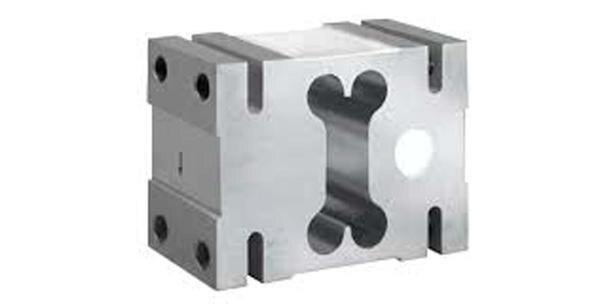
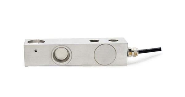
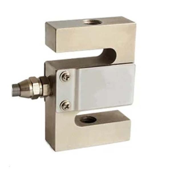
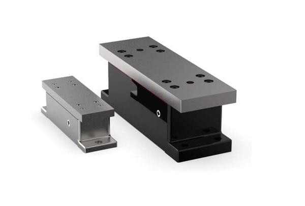
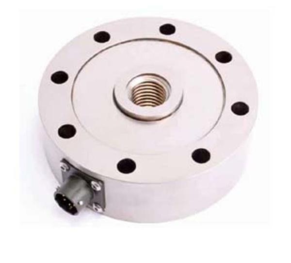
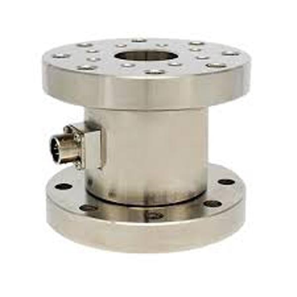
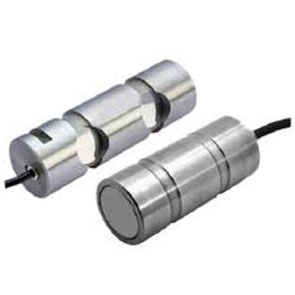
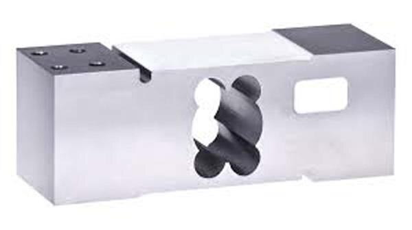
Load cells are ubiquitous in modern industry, serving as the unsung heroes behind countless measurement systems. From weighing scales in supermarkets to industrial process control, their ability to accurately convert force into an electrical signal is indispensable. Among the various materials employed in their construction, aluminum holds a unique and significant position. The aluminum load cell offers a compelling combination of lightweight design, excellent performance characteristics, and cost-effectiveness, making it a preferred choice for a vast array of applications. At its core, a load cell operates on the principle of strain gauge technology. When a force is applied to a carefully designed metallic element, known as the spring element or flexure, it undergoes deformation. Bonded to the surface of this element are one or more strain gauges – delicate electrical resistors whose resistance changes proportionally with their deformation. These strain gauges are typically arranged in a Wheatstone bridge configuration. This setup allows for the detection of even minute changes in resistance, converting them into a measurable voltage output that is directly proportional to the applied force. The Allure of Aluminum: Why Choose This Metal? While steel, particularly stainless steel, is a common material for high-capacity and harsh-environment load cells, aluminum offers distinct advantages that make it ideal for specific applications: Lightweight: This is perhaps the most obvious benefit. Aluminum's low density compared to steel significantly reduces the overall weight of the load cell. This is crucial in applications where weight is a critical factor, such as portable weighing devices, aerospace components, and robotics, where minimizing inertia is important. Lighter load cells are also easier to handle, transport, and install. Excellent Machinability: Aluminum is renowned for its ease of machining. This allows for intricate and precise designs of the load cell's flexure element, which is critical for achieving high accuracy and repeatability. Complex geometries, essential for optimizing stress distribution and isolating strain, can be manufactured with greater efficiency and lower cost compared to harder metals. Good Strength-to-Weight Ratio: Despite its lightness, certain aluminum alloys possess a high strength-to-weight ratio. This means they can withstand significant loads relative to their mass, making them suitable for a wide range of capacities, particularly in the lower to mid-range. Corrosion Resistance: While not as inherently corrosion-resistant as stainless steel, aluminum forms a passive oxide layer that provides a degree of protection against atmospheric corrosion. For many indoor and less aggressive outdoor environments, this is sufficient. Surface treatments like anodizing can further enhance its corrosion resistance and provide an aesthetic finish. Cost-Effectiveness: Generally, aluminum is more economical than stainless steel, contributing to the overall affordability of aluminum load cells. This makes them an attractive option for high-volume applications where cost efficiency is a key consideration. Good Thermal Conductivity: Aluminum's excellent thermal conductivity helps dissipate heat generated during operation, which can contribute to greater stability in readings, especially in environments with fluctuating temperatures. This is important for minimizing thermal errors. However, it's also important to acknowledge certain limitations. Aluminum is generally not suitable for extremely high-capacity applications where steel's superior yield strength and stiffness are indispensable. It can also be more susceptible to fatigue under very high cyclic loading compared to some specialized steels. For highly corrosive or abrasive environments, alternative materials or robust protective coatings might be necessary. Types and Applications of Aluminum Load Cells Aluminum load cells come in various configurations, each designed to optimize performance for specific force measurement scenarios: Single Point Load Cells: These are perhaps the most common type of aluminum load cell. They are designed to be insensitive to eccentric loading, meaning a load applied anywhere on the platform will yield the same output. This makes them ideal for platform scales, retail scales, packaging machines, and conveyor belt scales where the load's position can vary. Their compact design and ease of integration are significant advantages. Bending Beam Load Cells: Characterized by their rectangular or “S” shape, bending beam load cells typically have strain gauges mounted on the top and bottom surfaces of the beam. As force is applied, the beam bends, inducing tension on one side and compression on the other. They are frequently used in tank weighing, batching systems, and industrial weighing platforms. Shear Beam Load Cells: Similar to bending beams, but with strain gauges strategically placed to measure shear forces. They offer good accuracy and are less susceptible to side loads. Applications include floor scales, truck scales, and large industrial weighing systems. While often found in steel, smaller capacity shear beams can utilize aluminum. Miniature and Micro Load Cells: Leveraging aluminum's machinability and lightweight nature, these tiny load cells are designed for highly constrained spaces and low-force measurements. They are critical in medical devices, robotics, laboratory equipment, and consumer electronics where precision in a compact form factor is paramount. The versatility of aluminum load cells translates into an expansive range of applications across numerous industries: Retail and Commercial Weighing: From kitchen scales to pricing scales in grocery stores, aluminum single point load cells are the backbone of accurate commercial weighing. Industrial Automation: Packaging machines, filling systems, sorting equipment, and checkweighers rely heavily on aluminum load cells for precise weight control and process automation. Medical Devices: Infusion pumps, diagnostic equipment, and patient monitoring systems utilize miniature aluminum load cells for accurate force and weight measurements. Robotics: For end-effector force sensing, gripping force measurement, and collision detection, the lightweight nature of aluminum load cells is highly advantageous in robotic applications. Food Processing: Many food-grade weighing applications utilize aluminum load cells, often with appropriate coatings for hygiene and washdown environments. Test and Measurement: In laboratories and quality control settings, aluminum load cells are employed for material testing, force calibration, and product verification. We are also supply in Andhra Pradesh, Arunachal Pradesh, Assam, Bihar, Chhattisgarh, Goa, Gujarat, Haryana, Himachal Pradesh, Jharkhand, Karnataka, Kerala, Madhya Pradesh, Maharashtra, Manipur, Meghalaya, Mizoram, Nagaland, Odisha, Punjab, Rajasthan, Sikkim, Tamil Nadu, Telangana, Tripura, Uttar Pradesh, Uttarakhand, and West Bengal

Send Message
product image
SINGLE POINT LOAD CELL

Introduction Load cells are fundamental components in a vast array of weighing and force measurement systems, converting mechanical force into an electrical signal. While conventional load cells are designed to measure force applied along a specific axis, often at a single, central point, many real-world applications involve loads that are not perfectly centered. This challenge led to the development of off-center load cells, also commonly known as single point load cells. These specialized sensors are engineered to accurately measure a load regardless of its position on a weighing platform, within specified limits. Their unique design and internal compensation mechanisms make them indispensable for applications ranging from retail scales to industrial platforms, where the precise placement of an object cannot always be guaranteed. Basic Principle of Load Cells Before delving into off-center load cells, it's crucial to understand the fundamental working principle of a load cell. Most load cells operate on the principle of strain gauges. A strain gauge is a small, foil-based sensor whose electrical resistance changes proportionally when it is stretched or compressed (strained). A typical load cell body, often made of aluminum, steel, or stainless steel, is precisely machined to create a “flexure” or “spring element.” When a force is applied, this flexure deforms elastically. Strain gauges are strategically bonded to the surface of this flexure at points where the deformation (strain) is maximized. These strain gauges are then wired into a Wheatstone bridge circuit. A Wheatstone bridge is an electrical circuit used to measure an unknown electrical resistance by balancing two legs of a bridge circuit, one leg of which includes the unknown component. In a load cell, as the strain gauges deform, their resistance changes, unbalancing the bridge. This imbalance generates a small voltage output that is directly proportional to the applied force. This voltage signal is then amplified, digitized, and processed by an indicator or control system to display the weight or force. The Challenge of Off-Center Loading In many weighing applications, especially those involving platforms, the load is rarely applied perfectly at the center. Imagine a retail scale where a customer places an item anywhere on the pan, or an industrial platform scale where a pallet might be pushed to one side. If a standard, single-beam load cell were used in such a scenario, applying the load away from its central axis would introduce bending moments and shear forces that are not uniformly distributed across the strain gauges. This non-uniform stress distribution would lead to inaccurate readings, as the bridge output would vary depending on where the load was placed, even if the total weight remained constant. This phenomenon is known as “corner error” or “eccentric load error.” To overcome this, traditional multi-load cell systems would be required, using four or more standard load cells, one at each corner of the platform. While effective, this approach increases complexity, cost, and the number of components that can fail or go out of calibration. Design and Construction of Off-Center Load Cells Off-center load cells, primarily characterized by their “single point” design, are specifically engineered to counteract eccentric loading effects. They are typically block-shaped, often made from aluminum (for lower capacities) or stainless steel (for higher capacities and harsh environments). The key to their off-center compensation lies in: Rigid Body Design: Unlike simple bending beams, off-center load cells feature a more complex, often parallel-beam or shear-beam construction. The top and bottom surfaces are designed to remain parallel even under load, ensuring that the force is transmitted uniformly to the internal sensing elements. Multiple Strain Gauges and Strategic Placement: Instead of just two or four strain gauges, off-center load cells typically incorporate four or more active strain gauges. These gauges are precisely positioned on the internal flexure elements in such a way that any eccentric load causes a combination of tension and compression in different gauges. Internal Compensation: The genius of the off-center load cell lies in how these multiple strain gauges are wired into the Wheatstone bridge circuit. They are configured in a way that the effects of an off-center load on one set of gauges are precisely counteracted by the effects on another set. For example, if a load applied to one side causes a certain strain, the design ensures that a corresponding, opposite strain is induced in another part of the flexure, and the gauges sensing these strains are wired to cancel out the eccentric effect on the overall bridge output. This results in a net output that is solely proportional to the vertical component of the applied force, regardless of its horizontal position on the platform. The manufacturing process for these load cells is highly precise, involving advanced machining techniques to create the complex internal flexures and meticulous bonding of the strain gauges. This precision is critical to achieving the specified accuracy and off-center load compensation. How Off-Center Load Cells Compensate The compensation mechanism relies on a sophisticated arrangement of strain gauges within the Wheatstone bridge. Consider a common single point load cell design: Four Active Gauges: Typically, four active strain gauges are used. These are positioned on the internal web or shear elements of the load cell. Bridge Configuration: The gauges are wired into a full Wheatstone bridge. When a load is applied centrally, all gauges experience a predictable strain, leading to a proportional output. Eccentric Load Effect: When an eccentric load is applied (e.g., towards one end of the load cell's platform), it introduces a bending moment in addition to the vertical force. This bending moment would normally cause uneven strain across the gauges. Self-Correction: The unique placement and wiring ensure that the strains caused by the bending moment are effectively “cancelled out” within the bridge. For instance, if the eccentric load causes one gauge to experience increased tension and another to experience increased compression due to the bending, the bridge is wired so that these opposing effects negate each other in the final output signal. The only remaining, uncancelled effect is that due to the pure vertical force, leading to an accurate reading irrespective of load position. This internal compensation allows a single off-center load cell to support a relatively large weighing platform (often up to 600x600mm or more, depending on the load cell's capacity and design) and provide accurate readings across its entire surface. Advantages of Off-Center Load Cells The distinct design of off-center load cells offers several significant advantages: Accuracy with Eccentric Loads: This is their primary benefit. They provide highly accurate measurements even when the load is not centrally placed on the weighing platform, minimizing “corner error.” Simplified Mechanical Design: For platform scales, only a single off-center load cell is required, eliminating the need for complex mechanical linkages or multiple standard load cells. This simplifies the scale's construction, reduces material costs, and makes assembly easier. Cost-Effectiveness: While a single off-center load cell might be more expensive than a single standard load cell, it is often more cost-effective than a system requiring four or more standard load cells, along with summing boxes and mounting hardware. Reduced Footprint: The ability to use a single load cell allows for more compact and streamlined scale designs, which is crucial in applications with limited space. Easier Calibration and Maintenance: With only one load cell, calibration procedures are simplified, and troubleshooting potential issues becomes less complex. Applications Off-center load cells are widely used across various industries due to their versatility and accuracy in handling eccentric loads: Platform Scales: This is their most common application, including retail scales (checkout scales), postal scales, bench scales, and small to medium-sized industrial platform scales. Weighing Hoppers and Tanks: Used in process control to measure the contents of hoppers, tanks, and silos, where the material might settle unevenly. Packaging Machinery: Integrated into automated packaging lines to accurately weigh products as they are filled or packaged. Conveyor Belt Weighing: While often using specialized designs, the principle of compensating for distributed or uneven loads is similar. Medical Devices: Found in patient weighing scales, laboratory balances, and other medical equipment requiring precise and reliable weight measurement. Checkweighers: Essential for high-speed checkweighing applications where products move rapidly across a platform and need to be weighed accurately on the fly. Key Considerations for Selection and Installation When selecting and installing off-center load cells, several factors must be considered to ensure optimal performance: Capacity: Choose a load cell with a capacity that comfortably exceeds the maximum expected load, including any tare weight. Overloading can cause permanent damage. Accuracy Class: Load cells are classified by their accuracy (e.g., OIML R60 classes). Select a class appropriate for the required precision of the application. Platform Size: The maximum recommended platform size for a given off-center load cell is crucial. Exceeding this size can compromise off-center compensation. Material and Environmental Factors: Consider the operating environment. Stainless steel load cells with high IP ratings (Ingress Protection) are suitable for harsh, wet, or corrosive conditions. Aluminum is often used for dry, indoor applications. Mounting: Proper mounting is critical. The load cell must be installed on a rigid, level surface, and the platform should be securely attached without introducing any binding or side forces. Anti-lift-off devices or overload protection may be necessary. Calibration: Regular calibration with certified test weights is essential to maintain accuracy over time. Cable Length and Shielding: Ensure the cable length is adequate and that it is properly shielded to prevent electromagnetic interference (EMI) from affecting the signal. Maintenance and Troubleshooting Like any precision instrument, off-center load cells require proper maintenance and occasional troubleshooting: Regular Checks: Periodically inspect the load cell and its mounting for any signs of damage, corrosion, or loose connections. Cleanliness: Keep the area around the load cell clean, especially preventing debris from accumulating between the load cell and the platform, which can cause binding. Overload Protection: Ensure that any overload protection mechanisms are functioning correctly to prevent damage from excessive loads. Moisture Ingress: For load cells in wet environments, regularly check the integrity of cable glands and seals to prevent moisture ingress, which can lead to signal drift or failure. Troubleshooting: Common issues include unstable readings (often due to vibration, binding, or EMI), zero drift (temperature changes, creep, or mechanical issues), and inaccurate readings (calibration issues, overload, or damage). A multimeter can be used to check bridge resistance and output voltage for basic diagnostics. Conclusion Off-center load cells are a testament to innovative engineering in the field of force measurement. By cleverly compensating for eccentric loading, they have revolutionized the design and functionality of weighing platforms, making accurate and reliable measurements possible in diverse real-world scenarios where perfect load placement is impractical or impossible. Their ability to simplify mechanical designs, reduce costs, and maintain high accuracy under varying load positions solidifies their role as an indispensable component in modern industrial, commercial, and medical weighing systems, contributing significantly to efficiency, quality control, and safety across countless applications. We are also supply in Andhra Pradesh, Arunachal Pradesh, Assam, Bihar, Chhattisgarh, Goa, Gujarat, Haryana, Himachal Pradesh, Jharkhand, Karnataka, Kerala, Madhya Pradesh, Maharashtra, Manipur, Meghalaya, Mizoram, Nagaland, Odisha, Punjab, Rajasthan, Sikkim, Tamil Nadu, Telangana, Tripura, Uttar Pradesh, Uttarakhand, and West Bengal

Send Message
product image
LOAD CELL

The single-ended shear beam load cell is a ubiquitous component in industrial weighing and force measurement applications, valued for its robust construction, accuracy, and relatively simple design. This comprehensive overview will delve into its operational principles, construction, applications, advantages, limitations, and key considerations for selection and use. Operational Principle: Shear Stress for Precision At the heart of the single-ended shear beam load cell's functionality lies the principle of shear stress. Unlike bending beam load cells that primarily rely on tensile or compressive stress on a beam, shear beam load cells are designed to measure the shear deformation of a carefully machined beam element. Imagine a rectangular beam fixed at one end and free at the other, where the force is applied. When a vertical force is applied to the free end, the beam experiences both bending and shear. However, the critical design aspect of a shear beam load cell is to ensure that the strain gauges are strategically placed in areas where the shear stress is dominant and relatively uniform, minimising the influence of bending moments. Typically, the load cell body is a single, monolithic piece of high-grade alloy steel or aluminium. Within this body, a specific section is machined to create a “shear web” or “shear area.” When a downward force is applied to the free end of the load cell (the “loading point”), this shear web deforms. Strain gauges, which are tiny electrical resistors whose resistance changes proportionally to applied strain, are bonded to this shear web. These strain gauges are typically arranged in a Wheatstone bridge configuration. This bridge consists of four strain gauges connected in a specific way to maximise sensitivity and compensate for temperature changes. As the shear web deforms under load, the resistance of the strain gauges changes. This change in resistance unbalances the Wheatstone bridge, producing a small electrical voltage output that is directly proportional to the applied load. This voltage, usually in millivolts (mV), is then amplified and converted into a measurable weight or force reading by a dedicated instrumentation system. Construction: A Blend of Durability and Precision The construction of a single-ended shear beam load cell is critical to its performance and longevity: Material: The body is typically made from high-strength materials like alloy steel (often nickel-plated for corrosion resistance), stainless steel (for harsh environments and food-grade applications), or aluminium (for lighter applications). The choice of material impacts the load cell's capacity, environmental resistance, and cost. Beam Element/Shear Web: This is the precisely machined section where the shear stress is concentrated. The dimensions and geometry of this element are crucial for the load cell's sensitivity, linearity, and repeatability. Strain Gauges: These are the sensing elements, typically foil-type strain gauges, bonded with specialised adhesives to the shear web. Their placement and orientation are meticulously planned to capture the shear strain accurately. Encapsulation/Sealing: Load cells are often used in challenging industrial environments. Therefore, robust sealing is essential to protect the internal components (strain gauges and wiring) from moisture, dust, chemicals, and other contaminants. This is achieved through hermetic sealing (welding), potting compounds, or a combination of both, often resulting in an ingress protection (IP) rating (e.g., IP67, IP68). Mounting Holes: These are precision-drilled holes on both the fixed and loading ends, allowing for secure attachment to the weighing structure or application. Cable Gland and Cable: A durable cable gland ensures a sealed entry point for the electrical cable, which transmits the output signal to the weighing indicator or control system. The cable itself is typically shielded to minimise electrical interference. Applications: Versatility in Weighing and Force Measurement The versatility of single-ended shear beam load cells makes them indispensable in a wide array of industries: Platform Scales: This is perhaps their most common application. Multiple shear beam load cells are used in conjunction to support the platform, providing accurate weight measurements for various goods. Tank and Hopper Weighing: They are ideal for measuring the contents of tanks, silos, and hoppers in industries such as chemical processing, food and beverage, agriculture, and construction. They are often mounted on compression load mounts to accommodate thermal expansion and contraction. Conveyor Belt Weighing: Integrated into conveyor systems, they measure the weight of materials as they are transported, crucial for inventory management and process control. Process Weighing: Used in batching systems, filling machines, and other automated processes where precise control over material quantities is required. Packaging Machinery: Essential for ensuring accurate filling of products into bags, boxes, or containers. Force Measurement: Beyond just weight, they are used to measure applied forces in testing rigs, material testing machines, and various industrial equipment. Medical Devices: In certain medical applications requiring precise force sensing, albeit often with specialised designs and materials. Advantages: Why Choose a Single-Ended Shear Beam Load Cell? Several compelling advantages contribute to the widespread adoption of this load cell type: High Accuracy and Repeatability: Their design inherently provides excellent linearity and minimal hysteresis, leading to precise and consistent measurements. Robust and Durable: The solid, monolithic construction makes them highly resistant to shock loads, vibration, and general industrial abuse. Good Side Load Rejection: While not immune to side loads, their design generally offers better rejection of off-center or eccentric loading compared to some other load cell types, especially when used with proper mounting hardware. Relatively Compact Size: For their capacity, they are often quite compact, making them suitable for installations with limited space. Cost-Effective: Compared to some other high-precision load cell types, they offer a good balance of performance and cost. Ease of Installation: Their single-ended design simplifies mounting in many applications. Wide Range of Capacities: Available in a broad spectrum of capacities, from a few kilograms to several tons, catering to diverse weighing needs. Environmental Protection: Many models offer high IP ratings, making them suitable for use in washdown areas or dusty environments. Limitations and Considerations: Despite their advantages, it's important to be aware of certain limitations and key considerations: Sensitivity to Off-Center Loading (Though Better than Some): While good at rejecting side loads, extreme off-center loading can still introduce errors. Proper load application and mounting accessories (e.g., self-aligning feet, load buttons) are crucial. Temperature Effects: Like all strain gauge-based sensors, temperature fluctuations can affect accuracy. High-quality load cells incorporate temperature compensation, but extreme temperature swings can still be a factor. Dynamic Loading: While robust, continuous high-frequency dynamic loading can eventually lead to fatigue failure. For applications with rapid force changes, dynamic load cells might be more suitable. Creep: Over extended periods under constant load, a small, gradual change in output (creep) can occur. Reputable manufacturers specify creep specifications, and it's generally minimal in quality load cells. Overload Protection: Exceeding the rated capacity can permanently damage the load cell. Implementing mechanical overload stops or electronic overload protection is vital. Mounting Hardware: The performance of a shear beam load cell is heavily dependent on proper mounting. Using appropriate load cell mounts, self-aligning feet, and ensuring a rigid, level foundation is critical to achieving accurate results. Selection Criteria: When selecting a single-ended shear beam load cell, several factors must be carefully considered: Capacity: Determine the maximum expected load, including any potential overloads. Choose a load cell with sufficient capacity to avoid damage. Accuracy Requirements: Consider the required precision for the application (e.g., legal-for-trade, process control). Environmental Conditions: Evaluate temperature range, humidity, presence of dust, moisture, chemicals, and corrosive agents. This will dictate the required IP rating and material (e.g., stainless steel for washdown). Mounting Configuration: Assess how the load cell will be integrated into the system and select a model compatible with the mounting structure. Output Signal: Most shear beam load cells have a millivolt output, requiring an amplifier and indicator. Cable Length and Type: Consider the distance to the instrumentation and potential electrical interference. Manufacturer Reputation and Support: Choose a reputable manufacturer known for quality, reliability, and good technical support. We are also supply in Andhra Pradesh, Arunachal Pradesh, Assam, Bihar, Chhattisgarh, Goa, Gujarat, Haryana, Himachal Pradesh, Jharkhand, Karnataka, Kerala, Madhya Pradesh, Maharashtra, Manipur, Meghalaya, Mizoram, Nagaland, Odisha, Punjab, Rajasthan, Sikkim, Tamil Nadu, Telangana, Tripura, Uttar Pradesh, Uttarakhand, and West Bengal.

Send Message
product image
S BEAM

S Beam Load Cell Manufacturers We are also supply in Andhra Pradesh, Arunachal Pradesh, Assam, Bihar, Chhattisgarh, Goa, Gujarat, Haryana, Himachal Pradesh, Jharkhand, Karnataka, Kerala, Madhya Pradesh, Maharashtra, Manipur, Meghalaya, Mizoram, Nagaland, Odisha, Punjab, Rajasthan, Sikkim, Tamil Nadu, Telangana, Tripura, Uttar Pradesh, Uttarakhand, and West Bengal An S-Beam load cell, also known as an S-type or Z-beam load cell, is a type of force sensor named for its distinctive “S” shape. It is highly versatile and widely used in industrial and commercial applications to measure both tension and compression forces. How it works: The fundamental principle behind an S-beam load cell is the conversion of mechanical force into an electrical signal. Sensing Element: At its core, an S-beam load cell consists of a precisely machined metal body, often made of alloy steel or stainless steel, which acts as a spring element. This central beam is designed to deform elastically (bend or stretch) when a force is applied and return to its original shape when the force is removed. Strain Gauges: Attached to the surface of this central beam are highly sensitive electrical components called strain gauges. These thin, flexible devices have an electrical resistance that changes proportionally to the amount of strain (deformation) they experience. Wheatstone Bridge: The strain gauges are typically arranged in a Wheatstone bridge configuration. This circuit is extremely sensitive to small changes in resistance. Signal Generation: When a force (tension or compression) is applied to the S-beam load cell, the metal body deforms. This deformation causes the strain gauges to stretch or compress, which in turn changes their electrical resistance. Electrical Output: The change in resistance within the Wheatstone bridge unbalances the circuit, generating a measurable electrical signal (a voltage change). This electrical signal is directly proportional to the applied force. Signal Conditioning: This raw electrical signal is usually very small and needs to be amplified and processed by signal conditioning equipment (like amplifiers, filters, or analog-to-digital converters) to convert it into a usable format, such as a digital reading or an analog output. Key Features and Advantages: Dual Functionality: Measures both tension (pulling force) and compression (pushing force). High Accuracy: Known for providing precise measurements across a wide range of loads. Compact Design: Their S-shape often allows for a compact footprint, making them suitable for applications with limited space. Robust Construction: Typically made from durable materials like alloy steel or stainless steel, offering good resistance to harsh environments. Versatility: Can be used with various accessories like rod ends and load buttons for different mounting and application needs. Applications: S-beam load cells are incredibly versatile and find use in a wide array of industries and applications, including: Weighing Systems: Industrial scales (platform scales, hanging scales) Tank and hopper weighing systems (for liquids, powders, bulk materials) Conveyor belt weighing Batching plants Force Measurement: Material testing (tensile strength, compression testing) Cranes and hoists (for monitoring loads) Medical devices (e.g., patient lifting systems, grip force measurement, fluid flow rate) Robotics and automation Automotive testing Furniture testing Fatigue testing Process Control: Monitoring and controlling forces in manufacturing processes Quality control Overload protection in machinery Manufacturers and Pricing in India: Many manufacturers and suppliers offer S-beam load cells in India. Some common brands you might encounter include: You can find S-beam load cells from various vendors on platforms like IndiaMART. Pricing can vary significantly based on: Capacity: Ranging from a few kilograms to several tons. Material: Alloy steel is generally more economical, while stainless steel (often for corrosive or harsh environments) can be more expensive. Accuracy Class/Ingress Protection (IP Rating): Higher accuracy and better environmental sealing (e.g., IP68 for submersible applications) will increase the cost. Brand: Renowned international brands might have higher price points. Features: Overload protection, temperature compensation, and specific certifications can affect the price. As a general idea, based on current listings (as of July 2025), S-beam load cells in India can range from approximately ₹1,800 to ₹15,000 or more, depending on the specifications. For accurate pricing, it's best to contact specific suppliers and request quotes based on your exact requirements.

Send Message
product image
Force Transducer

Master Your Production with Precision: The Definitive Guide to Web Tension Load Cells In the fast-paced world of modern manufacturing, where precision, efficiency, and quality are paramount, subtle yet critical factors can make or break a production line. Among these, web tension control stands out as a fundamental requirement across diverse industries. From delicate films to robust textiles, maintaining optimal tension is the secret ingredient for flawless end products, reduced waste, and maximized throughput. At the heart of this crucial process lies the web tension load cell – a highly specialized sensor designed to accurately measure and control the pulling force on continuous materials. This comprehensive guide will delve deep into the world of web tension load cells, exploring their working principles, diverse applications, undeniable benefits, types, and essential considerations for selection, installation, and calibration. Whether you're a manufacturer in the printing, packaging, textile, or converting industry, understanding and leveraging the power of web tension load cells is key to unlocking superior performance and profitability. What is a Web Tension Load Cell and How Does It Work? A web tension load cell is a sophisticated force sensor specifically engineered to measure the tension or pulling force applied to a continuous sheet or web of material as it moves through a processing line. Unlike conventional load cells designed for general weighing or compression, web tension load cells are optimized for precise detection of relatively low forces in dynamic web handling environments. The core principle behind most web tension load cells is the strain gauge technology. Here's a simplified breakdown of how they operate: Sensing Beam/Element: The load cell incorporates a meticulously designed sensing element, often a bending beam or a differential bending beam, which is strategically positioned to come into contact with the web or roller supporting the web. Strain Gauges: Tiny electrical resistors called strain gauges are precisely bonded to this sensing element. These gauges are highly sensitive to minute deformations. Force to Deformation: As the web exerts tension on the roller, the sensing element within the load cell experiences a slight deformation or strain. Resistance Change: This deformation causes the strain gauges to stretch or compress, leading to a proportional change in their electrical resistance. Electrical Signal: These changes in resistance are then converted into a measurable electrical signal (typically a voltage change) by a Wheatstone bridge circuit. Signal Processing: The electrical signal, often in millivolts (mV), is then amplified by a load cell amplifier and transmitted to a tension controller. Real-time Feedback & Control: The tension controller processes this signal, compares it to a pre-set tension target, and then sends corrective signals to actuators like brakes, motors, or clutches. This creates a closed-loop control system, continuously adjusting the tension to maintain the desired level. This real-time feedback loop is crucial for preventing material defects, optimizing machine speed, and ensuring consistent product quality. Why Are Web Tension Load Cells Indispensable? The Benefits Unleashed The precise control offered by web tension load cells translates into a multitude of significant benefits for manufacturers: Superior Product Quality: This is arguably the most critical advantage. Consistent web tension prevents a host of defects such as wrinkling, creasing, stretching, tearing, misregistration in printing, and uneven coating. This leads to a higher quality end product that meets stringent specifications and reduces customer complaints. Reduced Material Waste: By preventing material damage and ensuring optimal processing, web tension load cells drastically cut down on scrap and rework, leading to substantial cost savings. Increased Production Efficiency and Throughput: With stable tension, machines can operate at higher speeds without fear of web breaks or material handling issues. This maximizes production capacity and reduces downtime. Enhanced Machine Uptime and Longevity: By preventing excessive stress on machinery components due to uncontrolled tension, load cells contribute to smoother operation, reduced wear and tear, and extended lifespan of equipment. Optimized Process Control: Real-time feedback allows for dynamic adjustments, adapting to changes in material properties, machine speed, or environmental conditions, ensuring consistent performance throughout the production run. Greater Automation Compatibility: Web tension load cells seamlessly integrate with modern PLC and SCADA systems, enabling fully automated tension control, minimizing manual intervention, and freeing up operators for other critical tasks. Data Logging and Analysis: Many advanced load cell systems offer data logging capabilities, providing valuable insights into tension profiles over time. This data can be used for process optimization, troubleshooting, and predictive maintenance. Improved Safety: By preventing web breaks and sudden tension fluctuations, load cells contribute to a safer working environment for operators. Diverse Applications Across Industries Web tension load cells are the unsung heroes in a wide array of industries that handle continuous web materials: Printing Industry: Critical for maintaining consistent registration, preventing paper breaks, and ensuring high-quality print on paper, film, and foil in flexographic, offset, digital, and gravure printing presses. Packaging Industry: Essential for controlling tension in films, foils, and laminates during processes like laminating, slitting, rewinding, form-fill-seal operations, and label manufacturing. Textile Industry: Used in weaving, knitting, coating, and finishing processes to maintain even yarn and fabric tension, preventing irregularities, snags, and ensuring consistent fabric quality. Converting Industry: Broadly encompasses various processes like slitting, rewinding, coating, laminating, and embossing of paper, plastic films, non-wovens, and metal foils. Plastic Film Extrusion: Crucial for controlling tension in blown film and cast film lines to ensure uniform thickness and consistent material properties. Wire and Cable Manufacturing: Employed to monitor and control tension during wire drawing, stranding, and winding operations, preventing breakage and ensuring product integrity. Tyre Manufacturing: Used in various stages involving rubber sheeting and cord winding to maintain precise tension. Battery Production: Involves coating and slitting processes where consistent tension of electrode materials is vital for battery performance. Types of Web Tension Load Cells While the underlying principle of strain gauge technology remains common, web tension load cells come in various forms to suit different installation requirements and applications: Pillow Block Load Cells: These are commonly integrated directly into the machine frame, often replacing or complementing existing pillow block bearings. They measure the horizontal and/or vertical forces exerted by the roller shaft. Flange Mounted Load Cells: Designed for easy installation, these load cells are typically mounted to a machine frame with a flange, providing a direct measurement point for web tension. Cantilever Load Cells: Often used in applications with single-sided web support, these compact load cells are ideal for measuring tension in narrow webs or on cantilevered rollers. Through-Shaft Load Cells: These load cells are designed to fit directly onto the shaft of the roller, offering a compact and direct measurement solution. Sensor Rollers: These are specialized rollers with integrated load cell technology, offering a self-contained and often simpler installation for tension measurement. Flat Load Cells: Compact and low-profile designs that fit into tight spaces, measuring tension across a flat surface. Round/Axial Load Cells: Designed for specific mounting configurations, often to measure tension along an axial direction. The choice of load cell type depends on factors like available space, roller configuration, web width, tension range, and environmental conditions. Selection, Installation, and Calibration: Key Considerations To maximize the performance and lifespan of your web tension load cells, consider these vital aspects: Selection: Tension Range: Crucial to match the load cell's capacity to the expected tension range of your application. Overloading can damage the sensor, while an undersized sensor may lack sensitivity. Accuracy and Sensitivity: High precision is key for optimal control. Look for specifications like non-linearity, hysteresis, and repeatability. Environmental Factors: Consider operating temperature, humidity, dust, and potential for corrosive elements. Choose load cells with appropriate IP ratings and material construction (e.g., stainless steel for harsh environments). Mounting Configuration: Ensure the load cell type is compatible with your machine's design and roller setup. Output Signal: Most load cells provide a mV/V output, which needs to be compatible with your tension controller. Overload Protection: Important for safeguarding the load cell from accidental damage due to sudden force spikes. Installation: Proper Alignment: Incorrect alignment is a common cause of inaccurate readings. Ensure the load cell is perfectly aligned with the direction of the web tension. Rigid Mounting: The mounting surface must be stable and rigid to prevent extraneous forces from affecting measurements. Cable Routing: Protect sensor cables from mechanical damage, electrical interference (EMC), and extreme temperatures. Use shielded cables where necessary. Manufacturer Guidelines: Always strictly follow the manufacturer's installation instructions for optimal performance and longevity. Calibration: Regular Calibration: Load cells, like any precision instrument, require periodic calibration to maintain accuracy and compensate for potential drift over time. Zeroing: Before applying any tension, the load cell system must be “zeroed” to account for any residual load or tare weight. Multi-point Calibration: For optimal accuracy, perform calibration at multiple points across the expected tension range using certified calibration weights or known forces. Professional Calibration: For critical applications, consider engaging professional calibration services to ensure compliance with industry standards. Documentation: Maintain detailed records of all calibration activities for traceability and quality assurance. The Future of Web Tension Control As industries move towards even greater automation and intelligent manufacturing, web tension load cells will continue to evolve. Advancements include: Enhanced Connectivity: Integration with Industrial IoT (IIoT) platforms for remote monitoring, predictive maintenance, and data analytics. Miniaturization: Smaller, more compact designs for integration into increasingly complex and space-constrained machinery. Advanced Materials: Development of new materials for improved durability, temperature stability, and higher overload capacities. AI and Machine Learning Integration: Leveraging AI for predictive tension control, anomaly detection, and self-optimization of web handling processes. Partnering for Precision Choosing the right web tension load cell and implementing an effective tension control system is a crucial investment for any manufacturer aiming for superior product quality and operational excellence. By understanding the principles, benefits, and considerations outlined in this guide, you can make informed decisions that drive efficiency, reduce waste, and ultimately, elevate your production capabilities. Partner with reputable manufacturers and suppliers who can provide not only high-quality web tension load cells but also expert advice, technical support, and comprehensive after-sales service. Your journey towards mastering web tension control starts here. We are also supply in Andhra Pradesh, Arunachal Pradesh, Assam, Bihar, Chhattisgarh, Goa, Gujarat, Haryana, Himachal Pradesh, Jharkhand, Karnataka, Kerala, Madhya Pradesh, Maharashtra, Manipur, Meghalaya, Mizoram, Nagaland, Odisha, Punjab, Rajasthan, Sikkim, Tamil Nadu, Telangana, Tripura, Uttar Pradesh, Uttarakhand, and West Bengal

Send Message
product image
COMPRESSION LOAD CELL

Pillow Block Type Load Cell – Accurate Load Measurement for Rotating Equipment Introduction to Pillow Block Type Load Cells In the realm of industrial automation and precision weighing, the pillow block type load cell has emerged as a critical component for accurate force measurement. These specialized load cells are designed to measure the load or force applied through rotating shafts or pillow block bearings, commonly found in conveyor systems, belt-driven machinery, and rotating equipment. The integration of load cells into pillow blocks offers a compact, efficient, and reliable way to monitor mechanical loads in real-time. Their design supports direct mounting under existing pillow block bearings, making them a preferred choice in applications where downtime and modifications must be minimized. What Is a Pillow Block Load Cell? A pillow block load cell is a type of force sensor that is installed beneath a pillow block bearing. Pillow blocks are used to provide support for a rotating shaft and maintain its alignment, typically in heavy-duty industrial machinery. The load cell measures the force transmitted through the bearing, often in vertical or horizontal directions, depending on the mounting orientation. Unlike conventional load cells that may require complex mounting and calibration, pillow block type load cells are engineered to seamlessly fit under standard pillow block bearing housings, offering plug-and-play functionality. How Does a Pillow Block Load Cell Work? These load cells operate on the principle of strain gauge technology, where mechanical deformation under load is converted into an electrical signal. When the shaft and its attached bearing exert force onto the pillow block, the internal sensing elements in the load cell detect the strain and output a proportional electrical signal. The signal can be processed by a weighing controller or PLC (Programmable Logic Controller) to monitor loads in real-time. The result is precise, consistent data that helps in performance monitoring, overload protection, and weight-based control of materials. Key Features and Benefits 1. Easy Installation Pillow block load cells are designed to fit under existing pillow block bearings without significant modifications. Their low-profile and rugged design makes installation simple and quick. 2. High Accuracy These load cells provide excellent measurement accuracy with minimal drift, even in dynamic conditions. They are suitable for both static and dynamic load applications. 3. Robust Construction Typically made from stainless steel or alloy steel, pillow block load cells are built to withstand harsh industrial environments, including dust, moisture, and vibration. 4. Real-Time Load Monitoring Ideal for continuous processes, the real-time data provided helps prevent equipment failure due to overload and supports predictive maintenance strategies. 5. Compact and Space-Saving Their integration into the bearing system eliminates the need for separate weighing platforms or external sensors, saving space and reducing system complexity. Common Applications Pillow block type load cells are widely used in industries where rotating shafts, conveyors, and material handling systems are prevalent. Key applications include: Conveyor Belt Weighing Systems Measure load on belts and provide feedback to regulate feed rates and maintain optimal load balance. Paper and Textile Industries Monitor tension and pressure in rollers and shafts to ensure consistent product quality. Mining and Aggregate Processing Used in crushers, feeders, and screening systems to monitor mechanical load and reduce wear and tear. Food and Beverage Manufacturing Measure loads in high-speed packaging and material handling systems to maintain efficiency and reduce waste. Steel and Metal Fabrication Track mechanical stress on rotating shafts during manufacturing and assembly. Types of Pillow Block Load Cells Several types of pillow block load cells are available to suit specific applications: 1. Single-Axis Load Cells Measure force in one direction (typically vertical or horizontal) and are ideal for straightforward load monitoring tasks. 2. Multi-Axis Load Cells Measure force in multiple directions simultaneously, useful in complex systems where forces may act in more than one axis. 3. High-Temperature Load Cells Designed for environments with elevated temperatures such as metal processing and kilns. 4. Custom Load Cells Engineered to meet specific size, load range, and mounting requirements, often used in specialized OEM machinery. Factors to Consider When Choosing a Pillow Block Load Cell When selecting the right load cell for your application, consider the following: - Load Range Choose a load cell with a capacity that matches or slightly exceeds the maximum expected load. - Mounting Dimensions Ensure compatibility with the existing pillow block bearing system. - Environmental Conditions Consider protection ratings (IP67/IP68), temperature resistance, and corrosion resistance for your operating environment. - Output Signal Verify whether the system requires analog (e.g., 4–20 mA, mV/V) or digital output, depending on your data acquisition or PLC system. - Accuracy and Sensitivity Look for specifications such as non-linearity, hysteresis, and repeatability to ensure the level of precision required for your application. Installation and Maintenance Tips Proper installation and maintenance are crucial for optimal performance: Use flat, rigid mounting surfaces to prevent distortion. Align the load cell correctly with the direction of force. Avoid excessive torque during mounting to prevent damage. Regularly inspect cables and connectors for wear or damage. Calibrate the system periodically to maintain measurement accuracy. Conclusion The pillow block type load cell is a versatile, efficient solution for real-time load measurement in rotating equipment. Its ability to seamlessly integrate into existing bearing systems makes it an ideal choice for many industrial applications. Whether you're optimizing a conveyor line, monitoring roller tension, or implementing overload protection in heavy-duty equipment, this type of load cell delivers precision, reliability, and durability. With the growing need for automated, data-driven manufacturing, investing in accurate force measurement technology like pillow block load cells is a smart move for improving efficiency, safety, and equipment longevity. We are also supply in Andhra Pradesh, Arunachal Pradesh, Assam, Bihar, Chhattisgarh, Goa, Gujarat, Haryana, Himachal Pradesh, Jharkhand, Karnataka, Kerala, Madhya Pradesh, Maharashtra, Manipur, Meghalaya, Mizoram, Nagaland, Odisha, Punjab, Rajasthan, Sikkim, Tamil Nadu, Telangana, Tripura, Uttar Pradesh, Uttarakhand, and West Bengal

Send Message
product image
S BEAM

Pancake Load Cell: The Ultimate Guide for Precision Force Measurement In industries that rely heavily on accurate force measurement, the pancake load cell stands out as a robust and reliable solution. Also known as low-profile load cells, these devices are designed to offer precise force readings in both tension and compression applications. Whether you're working in aerospace, automotive, manufacturing, or testing environments, understanding how pancake load cells work—and how to choose the right one—is crucial for efficiency and safety. In this comprehensive guide, we’ll explore what a pancake load cell is, how it works, its key features, applications, and tips for selecting the right model for your needs. What Is a Pancake Load Cell? A pancake load cell is a type of force transducer designed with a flat, disc-like shape—hence the name “pancake.” These load cells are engineered to measure axial loads, either in tension or compression, and they are known for their high accuracy, low profile, and wide load capacity range (from a few kilograms to several tons). They are typically made from high-strength stainless steel or aluminum and feature strain gauge technology that converts applied mechanical force into an electrical signal. This allows precise force monitoring in various environments. Key Features of Pancake Load Cells Low Profile Design The compact, disc-shaped design makes pancake load cells ideal for applications with limited vertical space. Their flat geometry enables easy integration into machines and test setups. High Accuracy and Repeatability Due to their symmetrical design and central loading structure, these load cells deliver high linearity and repeatability, even in harsh conditions. Tension and Compression Measurement Pancake load cells are capable of measuring forces in both directions, making them highly versatile. Overload Protection Many models come with built-in overload protection, ensuring durability and minimizing damage from excessive loads. High Load Capacity Pancake load cells are available in various capacities, ranging from a few hundred pounds to over 500,000 pounds (or 250 tons). Customizable Options Manufacturers often provide custom mounting holes, integrated connectors, and environmental sealing (IP65, IP67, etc.) to suit specific applications. How Does a Pancake Load Cell Work? Pancake load cells operate on the strain gauge principle. Here’s a simplified breakdown of how they work: When a force is applied to the central hub of the load cell, it causes slight deformation in the metal body. This deformation is picked up by bonded strain gauges—tiny sensors that change resistance based on the amount of strain. The change in resistance is converted into a measurable electrical signal (typically in mV/V), which is then amplified and interpreted by a data acquisition system or digital display. The central loading mechanism ensures that force is evenly distributed, minimizing off-axis errors and enhancing accuracy. Common Applications of Pancake Load Cells Pancake load cells are used in a wide range of industries, including: 1. Automotive Testing Used for engine testing, brake testing, and chassis load measurement to ensure vehicle safety and performance. 2. Aerospace Ideal for structural testing, fatigue testing, and component validation under extreme conditions. 3. Industrial Automation In automated manufacturing lines, pancake load cells help monitor applied forces in robotic arms, press machines, and welding systems. 4. Material Testing Essential for tensile and compression testing of metals, plastics, and composites in R&D labs and quality control. 5. Construction and Structural Monitoring Used to monitor load distribution in bridges, support structures, and cranes. Advantages Over Other Load Cell Types While there are many types of load cells—such as S-beam, shear beam, and button load cells—pancake load cells offer unique advantages: Feature Pancake Load Cell S-Beam Load Cell Button Load Cell Load Direction Tension & Compression Tension & Compression Mostly Compression Accuracy Very High Medium to High Medium Profile Low Medium Very Low Capacity Range Broad Medium Low to Medium Mounting Requirements Central Bolt Threaded Rod Flat Surface Choosing the Right Pancake Load Cell When selecting a pancake load cell, consider the following factors: Load Capacity Choose a capacity that suits your expected force range but allows for potential overloads. Always factor in a safety margin. Environmental Conditions If used in outdoor or harsh industrial environments, opt for load cells with high IP ratings and corrosion-resistant materials. Mounting Requirements Make sure the load cell has the right mounting hole pattern and thread specifications for your setup. Output Signal Type Determine whether you need an analog output (e.g., mV/V, 4-20mA) or a digital output (e.g., RS485, USB) based on your data acquisition system. Cable and Connector Options Check whether the load cell comes with an integrated cable or detachable connector. In some cases, a shielded cable is important to reduce electrical noise. Calibration and Maintenance Tips To maintain the accuracy and longevity of your pancake load cell: Calibrate regularly using certified calibration weights or services. Avoid lateral forces or off-axis loading, which may affect performance. Inspect the load cell and mounting hardware for wear or misalignment. Store and handle with care, especially the sensor cable and connector area. Final Thoughts : A pancake load cell is a precision force measurement device known for its low profile, high accuracy, and versatility. Whether you're involved in R&D, industrial automation, or structural testing, these load cells offer reliable performance across a broad range of applications. When properly selected and maintained, a pancake load cell can be a long-term solution that enhances the accuracy and safety of your measurement systems.

Send Message
product image
TORQUE SENSOR

Understanding Flange Static Torque Sensors: Function, Benefits, and Industrial Applications In the world of precision measurement and industrial automation, torque sensors play a pivotal role. Among the various types of torque sensors, the flange static torque sensor stands out due to its accuracy, reliability, and suitability for static torque measurement applications. Whether you're working in automotive testing, mechanical engineering, or robotics, understanding how these sensors work and where to use them can give your operation a significant edge. In this comprehensive guide, we will explore what flange static torque sensors are, how they work, their benefits, and common use cases across industries. What Is a Flange Static Torque Sensor? A flange static torque sensor, also known as a non-rotating torque transducer, is a type of torque sensor specifically designed to measure static torque—that is, torque applied without rotational movement. Unlike dynamic torque sensors, which operate while the shaft is rotating, static torque sensors measure torque in a stationary setup. The term “flange” refers to the sensor’s design: it typically features flanged mounting points that make it easy to install between two non-rotating components. These flanges ensure the sensor remains fixed during operation, providing stable and accurate torque readings. How Does a Flange Static Torque Sensor Work? A flange static torque sensor measures torque using strain gauge technology. Here’s how the process typically works: Application of Torque: Torque is applied to the sensor via two connected flanges—one on the driving side and one on the driven side. Strain Gauge Response: The applied torque causes a minute deformation (strain) in the sensing element of the sensor. Signal Conversion: Strain gauges attached to the sensing element change their electrical resistance due to the deformation. This change is converted into a measurable electrical signal. Signal Conditioning: The raw signal is amplified and processed to produce a calibrated torque output, typically in units like Nm (Newton-meters), lb-ft, or kg-cm. This design allows for high sensitivity and low signal drift, making flange static torque sensors ideal for precise applications. Key Features of Flange Static Torque Sensors Flange static torque sensors are known for their robust construction and reliable performance. Key features include: High Accuracy: These sensors can achieve accuracies as high as ±0.1% of full scale. Non-Rotating Measurement: Perfect for applications where components do not rotate but still transmit torque. Robust Mounting: The flange design provides a secure and stable installation. Minimal Maintenance: Fewer moving parts mean lower maintenance requirements. Wide Measurement Range: Available in torque capacities from a few Nm to several thousand Nm. Advantages of Using Flange Static Torque Sensors Using a flange static torque sensor offers several advantages for engineers and manufacturers: 1. Precision Measurement These sensors are ideal for tasks that demand high-accuracy torque readings, such as calibration systems or material testing. 2. Stability and Durability The rigid flange mount minimizes vibration and mechanical play, leading to consistent and reliable readings over time. 3. Versatility They are suitable for a variety of environments—from clean laboratory conditions to rugged industrial settings. 4. Integration Flexibility Flange static torque sensors can easily be integrated into custom-built rigs, test benches, or production lines, thanks to standardized flange dimensions. 5. Long Service Life Due to the non-rotating nature and sturdy construction, these sensors have long operational lifespans, even under continuous use. Common Applications of Flange Static Torque Sensors Flange static torque sensors are used across numerous industries. Some of the most common applications include: 1. Automotive Testing Engine and transmission test rigs Brake testing systems Electric motor torque measurement 2. Aerospace Engineering Component stress testing Actuator torque verification Propulsion system development 3. Industrial Automation Robotics joint torque monitoring Assembly torque verification Valve and actuator testing 4. Research and Development Material fatigue testing Mechanical property characterization Torque-to-failure testing 5. Energy and Utilities Wind turbine load monitoring Hydraulic and pneumatic torque systems Choosing the Right Flange Static Torque Sensor Selecting the right flange static torque sensor for your application involves considering the following factors: 1. Torque Range Choose a sensor with a maximum capacity that slightly exceeds your expected peak torque to avoid overloading. 2. Accuracy Requirements Determine the level of precision your application requires. Higher precision usually comes with a higher price tag. 3. Mounting Configuration Ensure the sensor’s flange pattern matches your existing equipment or system design. 4. Environmental Conditions If your application is in a harsh environment (e.g., high temperature, moisture, or vibration), select a sensor with appropriate environmental protection (IP-rated). 5. Output Signal Type Common output signals include analog voltage (e.g., 0-5V), current (e.g., 4-20mA), or digital (e.g., RS485, CAN). Choose one compatible with your data acquisition system. Maintenance and Calibration Even though flange static torque sensors are durable, regular calibration is essential to maintain accuracy. Most manufacturers recommend recalibration every 12 to 24 months, depending on usage. Also, keep the sensor clean and inspect it periodically for signs of wear, especially at the flange mounting points and electrical connectors. Conclusion A flange static torque sensor is a vital tool for any application that requires precise, non-rotating torque measurement. Thanks to their accuracy, durability, and ease of integration, these sensors have become indispensable in automotive testing, aerospace development, industrial automation, and research environments. By understanding their function, benefits, and use cases, you can choose the right flange static torque sensor that not only meets but exceeds your project requirements. Whether you're an engineer, technician, or procurement specialist, investing in the right torque measurement technology ensures better performance, improved safety, and more reliable results. We are also supply in Andhra Pradesh, Arunachal Pradesh, Assam, Bihar, Chhattisgarh, Goa, Gujarat, Haryana, Himachal Pradesh, Jharkhand, Karnataka, Kerala, Madhya Pradesh, Maharashtra, Manipur, Meghalaya, Mizoram, Nagaland, Odisha, Punjab, Rajasthan, Sikkim, Tamil Nadu, Telangana, Tripura, Uttar Pradesh, Uttarakhand, and West Bengal

Send Message
product image
LOAD CELL

Load Pin Load Cell: Accurate Force Measurement Built into Your Structure In the world of industrial lifting, marine operations, and structural monitoring, knowing the exact load being applied to critical components is essential for safety and efficiency. One highly effective and space-efficient solution is the load pin load cell—a custom-engineered force-sensing pin that directly replaces standard structural pins in machinery or lifting systems. Whether used in cranes, winches, sheaves, or shackles, load pin load cells offer a discreet yet highly accurate way to monitor force in real-time, right at the point of load application. What Is a Load Pin Load Cell? A load pin load cell is a cylindrical pin equipped with strain gauges that measure shear force. It is designed to replace a regular clevis or pivot pin, providing force measurement without the need for external mounting or complex hardware. The load pin is typically installed in equipment such as crane hooks, shackles, pulleys, or lifting beams, where it bears load and simultaneously measures the tension or compression passing through it. Because of its direct integration, it's considered a space-saving, customized force measurement solution. How Does It Work? Internally, load pins use strain gauge technology, placed in cross-drilled holes within the pin’s body. When force is applied, the pin experiences shear stress, and the strain gauges detect the tiny deformations. These deformations are converted into an electrical signal, which is calibrated to reflect the actual load applied. Many modern load pin sensors also include amplifiers, signal conditioners, or wireless transmitters, making them easy to connect with digital displays, PLCs, or remote monitoring systems. Key Benefits of Load Pin Load Cells ✅ Space-Efficient Integration Since the load pin directly replaces existing structural pins, it requires no additional mounting brackets or external force sensors. ✅ High Accuracy Typical accuracy ranges from ±0.5% to ±1.0% of full scale, suitable for most industrial and marine applications. ✅ Customizable Design Load pin load cells can be customized in terms of diameter, length, capacity, and material to fit existing equipment and load conditions. ✅ Rugged and Reliable Made from stainless steel or high-strength alloy steel, load pins are designed for harsh environments, often sealed to IP67 or IP68 standards. ✅ Ideal for Shackle and Hoist Monitoring Used in load shackles, hoists, and towing systems, they provide real-time feedback without altering mechanical design. Common Applications Marine & Offshore Winches Crane Hooks and Booms Lifting Shackles Sheaves and Cable Tensioners Hydraulic Cylinder Pins Anchor Line Monitoring Conclusion The load pin load cell is a smart, compact, and highly effective force measurement solution for applications where space is limited and accuracy is critical. With its ability to integrate directly into mechanical structures, it provides real-time load data without the complexity of traditional load cells. For industries like marine, aerospace, heavy lifting, and manufacturing, load pins offer the perfect balance of precision, durability, and simplicity. If you're seeking a custom-engineered sensor that won’t compromise your equipment design, the load pin load cell may be the ideal choice. We are also supply in Andhra Pradesh, Arunachal Pradesh, Assam, Bihar, Chhattisgarh, Goa, Gujarat, Haryana, Himachal Pradesh, Jharkhand, Karnataka, Kerala, Madhya Pradesh, Maharashtra, Manipur, Meghalaya, Mizoram, Nagaland, Odisha, Punjab, Rajasthan, Sikkim, Tamil Nadu, Telangana, Tripura, Uttar Pradesh, Uttarakhand, and West Bengal

Send Message

Still searching for
rider centric electric mobility india?