Ahmedabad
+919157924641

'roll to roll manufacturing'

Items tagged with 'roll to roll manufacturing'

product image
TORQUE SENSOR

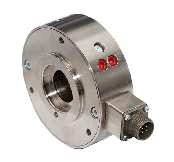
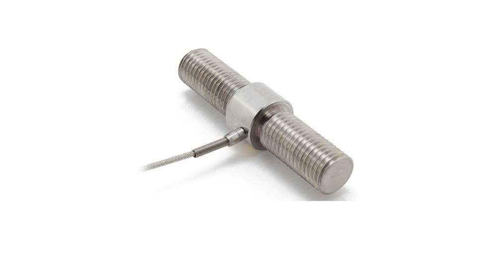
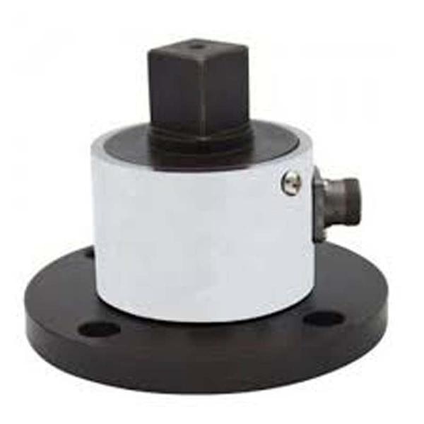
Square Drive Torque Sensor (Static): Accurate Torque Measurement for Tools and Calibration Introduction In industries where precise torque application is critical—such as automotive, aerospace, and manufacturing—reliable torque measurement tools are essential. One of the most trusted solutions for torque verification, especially for hand tools and torque wrenches, is the Static Square Drive Torque Sensor. Designed for non-rotating (static) torque measurement, square drive torque sensors offer unmatched accuracy and ease of integration for torque tool testing, calibration benches, and quality control systems. In this guide, we’ll explore the working principles, features, applications, and selection criteria of static square drive torque sensors. What is a Static Square Drive Torque Sensor? A Static Square Drive Torque Sensor is a non-rotating torque transducer designed to measure torque when it is applied without continuous rotation—commonly during the tightening or loosening of fasteners. The sensor features a standardized square drive interface (e.g., 1/4“, 3/8”, 1/2“, 3/4”, or 1“) that allows direct connection with torque tools like wrenches and drivers. These sensors are commonly used in torque calibration systems, tool verification stations, and R&D environments, where high-accuracy, bidirectional torque measurement is required. How Does a Square Drive Torque Sensor Work? The square drive torque sensor is based on strain gauge technology, which allows it to accurately measure static or semi-static torque forces. Here’s how it works: Torque Application: Torque is applied via the square drive interface by connecting a manual or powered tool. Shaft Deflection: The applied force causes a slight deformation (torsion) in the sensor’s internal shaft or element. Strain Gauge Response: Strain gauges detect this mechanical deformation and convert it into a change in electrical resistance. Signal Conditioning: The sensor's electronics convert this resistance change into an analog or digital output signal. Data Display: The output is then interpreted by a torque indicator, DAQ system, or calibration software to display the applied torque. Many models support clockwise and counterclockwise measurement, and some include overload protection or integrated displays. Key Features of Static Square Drive Torque Sensors ✅ Square Drive Interface: Standard sizes (e.g., 1/4”, 1/2“, 3/4”, 1“) for direct connection to torque tools. ✅ Static and Semi-Static Measurement: Designed for applications without continuous shaft rotation. ✅ High Accuracy: Typically ±0.1% to ±0.25% of full scale—ideal for calibration labs and QC. ✅ Bidirectional Measurement: Capable of measuring both tightening and loosening torque. ✅ Durable Construction: Made from hardened steel or stainless steel for industrial use. ✅ Multiple Output Options: mV/V, ±10V, 4-20mA, USB, RS-232, or CAN bus depending on the model. ✅ Calibration-Ready: Often supplied with NIST-traceable calibration certificates. Common Applications of Square Drive Torque Sensors 1. Torque Wrench Calibration Square drive torque sensors are integral to torque calibration benches for verifying and adjusting torque wrenches in compliance with ISO 6789 or other standards. 2. Assembly Tool Verification Used in quality control stations to test electric screwdrivers, pulse tools, and manual torque drivers before and after production shifts. 3. R&D and Testing Labs In automotive and aerospace R&D, static torque sensors are used for testing tool consistency, fastener performance, and joint reliability. 4. Production Line Spot Checks In-process torque verification using square drive sensors helps ensure torque traceability and tightening accuracy in manufacturing. 5. Maintenance and Calibration Labs Ideal for service and repair facilities that calibrate or verify tools as part of preventive maintenance. Advantages of Using a Static Square Drive Torque Sensor ✔️ Plug-and-Play Tool Compatibility The square drive design allows direct tool connection without adapters, simplifying setup. ✔️ High Precision for Non-Rotating Loads Ideal for applications that involve controlled torque application without continuous motion. ✔️ Compact and Portable Many sensors are lightweight and compact, making them suitable for both benchtop and mobile calibration kits. ✔️ Custom Ranges and Outputs Available in torque ranges from 0.1 Nm to 2000+ Nm, and can be customized with different electrical outputs for system integration. ✔️ Cost-Effective Calibration Solution Compared to full rotary torque sensors, static square drive models are more affordable for low-duty cycle or manual tool testing environments. Selecting the Right Square Drive Torque Sensor To choose the best sensor for your application, consider the following: 1. Torque Range Select a range that suits your tool or test application. Avoid exceeding the full-scale range to prevent sensor damage. 2. Drive Size Match the sensor's square drive to the tool being tested (e.g., 1/4”, 3/8“, 1/2”, 3/4“, or 1”). 3. Accuracy Requirements High-precision environments (like calibration labs) may need sensors with <±0.1% full-scale error. 4. Output Signal Type Choose a compatible signal for your data acquisition system (mV/V for direct strain gauge readout, or USB/analog for plug-and-play use). 5. Mounting and Setup Ensure the sensor fits your bench or calibration fixture. Some models come with baseplates or mounting accessories. 6. Certifications and Calibration Look for models with NIST-traceable certificates and ISO-compliant documentation for quality systems. Calibration and Maintenance Regular Calibration: To ensure accuracy, recalibrate sensors every 6–12 months, depending on usage. Avoid Overload: Use overload protection or load-limiting adapters when testing high-torque tools. Keep Connectors Clean: Protect electrical connections from dust, oil, or mechanical stress. Zero Adjustment: Always reset to zero before each test to remove drift or offset. Conclusion Static square drive torque sensors are the go-to solution for precise, non-rotating torque measurements in tool calibration, quality assurance, and research settings. With their easy-to-use square drive interface, robust construction, and exceptional accuracy, they offer a reliable and efficient method for maintaining torque tool integrity across industries. Whether you're running a calibration lab or verifying tools on the shop floor, integrating a square drive torque sensor into your process ensures compliance, repeatability, and trust in every fastening operation. We are also supply in Andhra Pradesh, Arunachal Pradesh, Assam, Bihar, Chhattisgarh, Goa, Gujarat, Haryana, Himachal Pradesh, Jharkhand, Karnataka, Kerala, Madhya Pradesh, Maharashtra, Manipur, Meghalaya, Mizoram, Nagaland, Odisha, Punjab, Rajasthan, Sikkim, Tamil Nadu, Telangana, Tripura, Uttar Pradesh, Uttarakhand, and West Bengal

Send Message
product image
Force Transducer

Master Your Production with Precision: The Definitive Guide to Web Tension Load Cells In the fast-paced world of modern manufacturing, where precision, efficiency, and quality are paramount, subtle yet critical factors can make or break a production line. Among these, web tension control stands out as a fundamental requirement across diverse industries. From delicate films to robust textiles, maintaining optimal tension is the secret ingredient for flawless end products, reduced waste, and maximized throughput. At the heart of this crucial process lies the web tension load cell – a highly specialized sensor designed to accurately measure and control the pulling force on continuous materials. This comprehensive guide will delve deep into the world of web tension load cells, exploring their working principles, diverse applications, undeniable benefits, types, and essential considerations for selection, installation, and calibration. Whether you're a manufacturer in the printing, packaging, textile, or converting industry, understanding and leveraging the power of web tension load cells is key to unlocking superior performance and profitability. What is a Web Tension Load Cell and How Does It Work? A web tension load cell is a sophisticated force sensor specifically engineered to measure the tension or pulling force applied to a continuous sheet or web of material as it moves through a processing line. Unlike conventional load cells designed for general weighing or compression, web tension load cells are optimized for precise detection of relatively low forces in dynamic web handling environments. The core principle behind most web tension load cells is the strain gauge technology. Here's a simplified breakdown of how they operate: Sensing Beam/Element: The load cell incorporates a meticulously designed sensing element, often a bending beam or a differential bending beam, which is strategically positioned to come into contact with the web or roller supporting the web. Strain Gauges: Tiny electrical resistors called strain gauges are precisely bonded to this sensing element. These gauges are highly sensitive to minute deformations. Force to Deformation: As the web exerts tension on the roller, the sensing element within the load cell experiences a slight deformation or strain. Resistance Change: This deformation causes the strain gauges to stretch or compress, leading to a proportional change in their electrical resistance. Electrical Signal: These changes in resistance are then converted into a measurable electrical signal (typically a voltage change) by a Wheatstone bridge circuit. Signal Processing: The electrical signal, often in millivolts (mV), is then amplified by a load cell amplifier and transmitted to a tension controller. Real-time Feedback & Control: The tension controller processes this signal, compares it to a pre-set tension target, and then sends corrective signals to actuators like brakes, motors, or clutches. This creates a closed-loop control system, continuously adjusting the tension to maintain the desired level. This real-time feedback loop is crucial for preventing material defects, optimizing machine speed, and ensuring consistent product quality. Why Are Web Tension Load Cells Indispensable? The Benefits Unleashed The precise control offered by web tension load cells translates into a multitude of significant benefits for manufacturers: Superior Product Quality: This is arguably the most critical advantage. Consistent web tension prevents a host of defects such as wrinkling, creasing, stretching, tearing, misregistration in printing, and uneven coating. This leads to a higher quality end product that meets stringent specifications and reduces customer complaints. Reduced Material Waste: By preventing material damage and ensuring optimal processing, web tension load cells drastically cut down on scrap and rework, leading to substantial cost savings. Increased Production Efficiency and Throughput: With stable tension, machines can operate at higher speeds without fear of web breaks or material handling issues. This maximizes production capacity and reduces downtime. Enhanced Machine Uptime and Longevity: By preventing excessive stress on machinery components due to uncontrolled tension, load cells contribute to smoother operation, reduced wear and tear, and extended lifespan of equipment. Optimized Process Control: Real-time feedback allows for dynamic adjustments, adapting to changes in material properties, machine speed, or environmental conditions, ensuring consistent performance throughout the production run. Greater Automation Compatibility: Web tension load cells seamlessly integrate with modern PLC and SCADA systems, enabling fully automated tension control, minimizing manual intervention, and freeing up operators for other critical tasks. Data Logging and Analysis: Many advanced load cell systems offer data logging capabilities, providing valuable insights into tension profiles over time. This data can be used for process optimization, troubleshooting, and predictive maintenance. Improved Safety: By preventing web breaks and sudden tension fluctuations, load cells contribute to a safer working environment for operators. Diverse Applications Across Industries Web tension load cells are the unsung heroes in a wide array of industries that handle continuous web materials: Printing Industry: Critical for maintaining consistent registration, preventing paper breaks, and ensuring high-quality print on paper, film, and foil in flexographic, offset, digital, and gravure printing presses. Packaging Industry: Essential for controlling tension in films, foils, and laminates during processes like laminating, slitting, rewinding, form-fill-seal operations, and label manufacturing. Textile Industry: Used in weaving, knitting, coating, and finishing processes to maintain even yarn and fabric tension, preventing irregularities, snags, and ensuring consistent fabric quality. Converting Industry: Broadly encompasses various processes like slitting, rewinding, coating, laminating, and embossing of paper, plastic films, non-wovens, and metal foils. Plastic Film Extrusion: Crucial for controlling tension in blown film and cast film lines to ensure uniform thickness and consistent material properties. Wire and Cable Manufacturing: Employed to monitor and control tension during wire drawing, stranding, and winding operations, preventing breakage and ensuring product integrity. Tyre Manufacturing: Used in various stages involving rubber sheeting and cord winding to maintain precise tension. Battery Production: Involves coating and slitting processes where consistent tension of electrode materials is vital for battery performance. Types of Web Tension Load Cells While the underlying principle of strain gauge technology remains common, web tension load cells come in various forms to suit different installation requirements and applications: Pillow Block Load Cells: These are commonly integrated directly into the machine frame, often replacing or complementing existing pillow block bearings. They measure the horizontal and/or vertical forces exerted by the roller shaft. Flange Mounted Load Cells: Designed for easy installation, these load cells are typically mounted to a machine frame with a flange, providing a direct measurement point for web tension. Cantilever Load Cells: Often used in applications with single-sided web support, these compact load cells are ideal for measuring tension in narrow webs or on cantilevered rollers. Through-Shaft Load Cells: These load cells are designed to fit directly onto the shaft of the roller, offering a compact and direct measurement solution. Sensor Rollers: These are specialized rollers with integrated load cell technology, offering a self-contained and often simpler installation for tension measurement. Flat Load Cells: Compact and low-profile designs that fit into tight spaces, measuring tension across a flat surface. Round/Axial Load Cells: Designed for specific mounting configurations, often to measure tension along an axial direction. The choice of load cell type depends on factors like available space, roller configuration, web width, tension range, and environmental conditions. Selection, Installation, and Calibration: Key Considerations To maximize the performance and lifespan of your web tension load cells, consider these vital aspects: Selection: Tension Range: Crucial to match the load cell's capacity to the expected tension range of your application. Overloading can damage the sensor, while an undersized sensor may lack sensitivity. Accuracy and Sensitivity: High precision is key for optimal control. Look for specifications like non-linearity, hysteresis, and repeatability. Environmental Factors: Consider operating temperature, humidity, dust, and potential for corrosive elements. Choose load cells with appropriate IP ratings and material construction (e.g., stainless steel for harsh environments). Mounting Configuration: Ensure the load cell type is compatible with your machine's design and roller setup. Output Signal: Most load cells provide a mV/V output, which needs to be compatible with your tension controller. Overload Protection: Important for safeguarding the load cell from accidental damage due to sudden force spikes. Installation: Proper Alignment: Incorrect alignment is a common cause of inaccurate readings. Ensure the load cell is perfectly aligned with the direction of the web tension. Rigid Mounting: The mounting surface must be stable and rigid to prevent extraneous forces from affecting measurements. Cable Routing: Protect sensor cables from mechanical damage, electrical interference (EMC), and extreme temperatures. Use shielded cables where necessary. Manufacturer Guidelines: Always strictly follow the manufacturer's installation instructions for optimal performance and longevity. Calibration: Regular Calibration: Load cells, like any precision instrument, require periodic calibration to maintain accuracy and compensate for potential drift over time. Zeroing: Before applying any tension, the load cell system must be “zeroed” to account for any residual load or tare weight. Multi-point Calibration: For optimal accuracy, perform calibration at multiple points across the expected tension range using certified calibration weights or known forces. Professional Calibration: For critical applications, consider engaging professional calibration services to ensure compliance with industry standards. Documentation: Maintain detailed records of all calibration activities for traceability and quality assurance. The Future of Web Tension Control As industries move towards even greater automation and intelligent manufacturing, web tension load cells will continue to evolve. Advancements include: Enhanced Connectivity: Integration with Industrial IoT (IIoT) platforms for remote monitoring, predictive maintenance, and data analytics. Miniaturization: Smaller, more compact designs for integration into increasingly complex and space-constrained machinery. Advanced Materials: Development of new materials for improved durability, temperature stability, and higher overload capacities. AI and Machine Learning Integration: Leveraging AI for predictive tension control, anomaly detection, and self-optimization of web handling processes. Partnering for Precision Choosing the right web tension load cell and implementing an effective tension control system is a crucial investment for any manufacturer aiming for superior product quality and operational excellence. By understanding the principles, benefits, and considerations outlined in this guide, you can make informed decisions that drive efficiency, reduce waste, and ultimately, elevate your production capabilities. Partner with reputable manufacturers and suppliers who can provide not only high-quality web tension load cells but also expert advice, technical support, and comprehensive after-sales service. Your journey towards mastering web tension control starts here. We are also supply in Andhra Pradesh, Arunachal Pradesh, Assam, Bihar, Chhattisgarh, Goa, Gujarat, Haryana, Himachal Pradesh, Jharkhand, Karnataka, Kerala, Madhya Pradesh, Maharashtra, Manipur, Meghalaya, Mizoram, Nagaland, Odisha, Punjab, Rajasthan, Sikkim, Tamil Nadu, Telangana, Tripura, Uttar Pradesh, Uttarakhand, and West Bengal

Send Message
product image
COMPRESSION LOAD CELL

Pillow Block Type Load Cell – Accurate Load Measurement for Rotating Equipment Introduction to Pillow Block Type Load Cells In the realm of industrial automation and precision weighing, the pillow block type load cell has emerged as a critical component for accurate force measurement. These specialized load cells are designed to measure the load or force applied through rotating shafts or pillow block bearings, commonly found in conveyor systems, belt-driven machinery, and rotating equipment. The integration of load cells into pillow blocks offers a compact, efficient, and reliable way to monitor mechanical loads in real-time. Their design supports direct mounting under existing pillow block bearings, making them a preferred choice in applications where downtime and modifications must be minimized. What Is a Pillow Block Load Cell? A pillow block load cell is a type of force sensor that is installed beneath a pillow block bearing. Pillow blocks are used to provide support for a rotating shaft and maintain its alignment, typically in heavy-duty industrial machinery. The load cell measures the force transmitted through the bearing, often in vertical or horizontal directions, depending on the mounting orientation. Unlike conventional load cells that may require complex mounting and calibration, pillow block type load cells are engineered to seamlessly fit under standard pillow block bearing housings, offering plug-and-play functionality. How Does a Pillow Block Load Cell Work? These load cells operate on the principle of strain gauge technology, where mechanical deformation under load is converted into an electrical signal. When the shaft and its attached bearing exert force onto the pillow block, the internal sensing elements in the load cell detect the strain and output a proportional electrical signal. The signal can be processed by a weighing controller or PLC (Programmable Logic Controller) to monitor loads in real-time. The result is precise, consistent data that helps in performance monitoring, overload protection, and weight-based control of materials. Key Features and Benefits 1. Easy Installation Pillow block load cells are designed to fit under existing pillow block bearings without significant modifications. Their low-profile and rugged design makes installation simple and quick. 2. High Accuracy These load cells provide excellent measurement accuracy with minimal drift, even in dynamic conditions. They are suitable for both static and dynamic load applications. 3. Robust Construction Typically made from stainless steel or alloy steel, pillow block load cells are built to withstand harsh industrial environments, including dust, moisture, and vibration. 4. Real-Time Load Monitoring Ideal for continuous processes, the real-time data provided helps prevent equipment failure due to overload and supports predictive maintenance strategies. 5. Compact and Space-Saving Their integration into the bearing system eliminates the need for separate weighing platforms or external sensors, saving space and reducing system complexity. Common Applications Pillow block type load cells are widely used in industries where rotating shafts, conveyors, and material handling systems are prevalent. Key applications include: Conveyor Belt Weighing Systems Measure load on belts and provide feedback to regulate feed rates and maintain optimal load balance. Paper and Textile Industries Monitor tension and pressure in rollers and shafts to ensure consistent product quality. Mining and Aggregate Processing Used in crushers, feeders, and screening systems to monitor mechanical load and reduce wear and tear. Food and Beverage Manufacturing Measure loads in high-speed packaging and material handling systems to maintain efficiency and reduce waste. Steel and Metal Fabrication Track mechanical stress on rotating shafts during manufacturing and assembly. Types of Pillow Block Load Cells Several types of pillow block load cells are available to suit specific applications: 1. Single-Axis Load Cells Measure force in one direction (typically vertical or horizontal) and are ideal for straightforward load monitoring tasks. 2. Multi-Axis Load Cells Measure force in multiple directions simultaneously, useful in complex systems where forces may act in more than one axis. 3. High-Temperature Load Cells Designed for environments with elevated temperatures such as metal processing and kilns. 4. Custom Load Cells Engineered to meet specific size, load range, and mounting requirements, often used in specialized OEM machinery. Factors to Consider When Choosing a Pillow Block Load Cell When selecting the right load cell for your application, consider the following: - Load Range Choose a load cell with a capacity that matches or slightly exceeds the maximum expected load. - Mounting Dimensions Ensure compatibility with the existing pillow block bearing system. - Environmental Conditions Consider protection ratings (IP67/IP68), temperature resistance, and corrosion resistance for your operating environment. - Output Signal Verify whether the system requires analog (e.g., 4–20 mA, mV/V) or digital output, depending on your data acquisition or PLC system. - Accuracy and Sensitivity Look for specifications such as non-linearity, hysteresis, and repeatability to ensure the level of precision required for your application. Installation and Maintenance Tips Proper installation and maintenance are crucial for optimal performance: Use flat, rigid mounting surfaces to prevent distortion. Align the load cell correctly with the direction of force. Avoid excessive torque during mounting to prevent damage. Regularly inspect cables and connectors for wear or damage. Calibrate the system periodically to maintain measurement accuracy. Conclusion The pillow block type load cell is a versatile, efficient solution for real-time load measurement in rotating equipment. Its ability to seamlessly integrate into existing bearing systems makes it an ideal choice for many industrial applications. Whether you're optimizing a conveyor line, monitoring roller tension, or implementing overload protection in heavy-duty equipment, this type of load cell delivers precision, reliability, and durability. With the growing need for automated, data-driven manufacturing, investing in accurate force measurement technology like pillow block load cells is a smart move for improving efficiency, safety, and equipment longevity. We are also supply in Andhra Pradesh, Arunachal Pradesh, Assam, Bihar, Chhattisgarh, Goa, Gujarat, Haryana, Himachal Pradesh, Jharkhand, Karnataka, Kerala, Madhya Pradesh, Maharashtra, Manipur, Meghalaya, Mizoram, Nagaland, Odisha, Punjab, Rajasthan, Sikkim, Tamil Nadu, Telangana, Tripura, Uttar Pradesh, Uttarakhand, and West Bengal

Send Message
product image
COMPRESSION LOAD CELL

Introduction In modern engineering, robotics, and manufacturing industries, the need for compact, high-accuracy force sensors is greater than ever. One such sensor that stands out for its small form factor and excellent compression performance is the button load cell. Also known as a miniature compression load cell, this sensor type is ideal for applications with limited space but demanding precision. This comprehensive guide explores the design, function, benefits, and common uses of button load cells. We’ll also provide helpful tips for selecting the right sensor and include SEO-optimized keywords to improve visibility in search engines. What is a Button Load Cell? A button load cell is a small, disc-shaped force sensor designed primarily for compression force measurement. It gets its name from its resemblance to a flat button and is typically used in tight spaces where a traditional load cell won’t fit. Despite its compact size, a button load cell is capable of handling a wide range of forces—from a few Newtons up to several tons—while maintaining excellent accuracy and repeatability. How Button Load Cells Work Most button load cells operate using strain gauge technology. Here’s a breakdown of how they function: Force Application: A compressive force is applied to the center of the load cell's top surface. Strain Response: This force causes a slight deformation in the load cell's internal structure. Strain Gauge Reaction: Strain gauges bonded inside the sensor detect this deformation as a change in electrical resistance. Signal Conversion: The change in resistance is converted into an electrical signal (typically in mV/V), which is proportional to the force applied. Data Output: This signal can be fed into a data acquisition system (DAQ), amplifier, or display unit for real-time force monitoring. Key Features of Button Load Cells ✅ Ultra-Compact Design: Some models are as small as 5 mm in diameter. ✅ Compression-Only Measurement: Ideal for vertical load and press applications. ✅ Wide Capacity Range: Available in ranges from a few grams up to 100,000+ pounds. ✅ High Strength Materials: Constructed from stainless steel or alloy steel for industrial durability. ✅ High Accuracy and Repeatability: Ideal for precise, repeatable measurements in test environments. ✅ Low Deflection: Minimal deformation ensures fast response and high stiffness. Applications of Button Load Cells 1. Press Force Monitoring Used in manual and hydraulic presses to measure applied compressive forces during forming, stamping, or pressing processes. 2. Robotics and Automation In robot joints and end-effectors, button load cells provide compact force feedback to enhance control and safety. 3. Medical Device Testing Ideal for prosthetics, orthopedic implants, and surgical tools, where compact size and precision are vital. 4. Material Testing Machines Used in compression test rigs to measure the response of materials under load, such as in foam, rubber, and plastic testing. 5. R&D and Prototyping Engineers use button load cells in prototype builds where space is constrained but force feedback is needed. 6. Consumer Electronics Testing Used in testing the tactile force of keyboards, buttons, and touchscreens to ensure product consistency. Benefits of Using Button Load Cells ✔️ Space-Saving Installation The ultra-small footprint allows for integration in tight or embedded spaces without affecting the host device’s design. ✔️ Excellent Load Sensitivity Despite their small size, button load cells offer precise readings over a wide load range. ✔️ Easy Integration Flat-bottomed design allows for simple surface mounting or embedding into custom fixtures. ✔️ High Durability Built to withstand repeated use in industrial and lab environments without loss of accuracy. ✔️ Customizable Output Available with various signal output options, including: mV/V (standard strain gauge) 0–5V or 0–10V (amplified analog) 4–20mA (current loop) USB or digital (via external signal conditioner) Factors to Consider When Choosing a Button Load Cell 1. Force Capacity Choose a load cell that matches your expected maximum force. Always leave a safety margin to avoid overload. 2. Sensor Size Match the diameter and height of the sensor to your available space. 3. Mounting Method Ensure a stable, flat surface for installation. Some button load cells include threaded mounting holes or adhesive bases. 4. Output Signal Type Select a sensor with output compatible with your system—whether it's direct mV/V or amplified analog/digital. 5. Environmental Conditions If the sensor is used in wet, dusty, or high-temperature environments, look for models with IP-rated enclosures or environmental sealing. 6. Calibration Ensure the load cell comes with a NIST-traceable calibration certificate or equivalent. Regular calibration ensures long-term accuracy. Installation Tips Mount on Flat, Rigid Surfaces: Uneven surfaces may lead to incorrect readings. Avoid Lateral Loading: These sensors are designed for vertical (axial) compression only. Center the Load: Apply force directly to the center dome or button for best results. Use Load Pads if Needed: Some applications require load-distribution accessories to prevent damage from point loads. Protect Wiring: Strain-relieve cables and avoid sharp bends near the sensor body. Maintenance and Calibration Button load cells require minimal maintenance but should be checked periodically for: Physical damage or deformation Cable wear or signal interference Signal drift (zero-point shifting) Annual calibration is recommended for critical measurements, especially in regulated industries like aerospace or healthcare. Conclusion Button load cells are a vital part of the force measurement toolkit, especially in applications where size, accuracy, and simplicity matter. Whether you’re measuring press forces, embedding sensors in robotics, or testing medical devices, these compact compression sensors offer precision in a tiny package. With a variety of capacities, output types, and rugged designs, button load cells are suitable for both R&D and production environments. When selected and installed properly, they provide years of reliable, high-accuracy measurements in the most space-constrained settings. We are also supply in Andhra Pradesh, Arunachal Pradesh, Assam, Bihar, Chhattisgarh, Goa, Gujarat, Haryana, Himachal Pradesh, Jharkhand, Karnataka, Kerala, Madhya Pradesh, Maharashtra, Manipur, Meghalaya, Mizoram, Nagaland, Odisha, Punjab, Rajasthan, Sikkim, Tamil Nadu, Telangana, Tripura, Uttar Pradesh, Uttarakhand, and West Bengal

Send Message
product image
TORQUE SENSOR

In industries where rotating machinery is central—such as automotive, aerospace, robotics, and industrial automation—precise torque measurement is critical for performance, safety, and quality control. That’s where rotary torque sensors come into play. Also known as rotating torque transducers, these precision devices are designed to measure torque on a spinning shaft, delivering real-time data critical for testing, diagnostics, and control. This article provides a detailed overview of rotary torque sensors, including their working principle, types, applications, benefits, and factors to consider when selecting the right model for your system. What Is a Rotary Torque Sensor? A rotary torque sensor is a specialized instrument designed to measure the rotational force (torque) transmitted through a spinning shaft or system. Unlike static torque sensors, which measure torque on stationary systems, rotary sensors operate on moving shafts—often at high speeds. These sensors are vital in systems that involve motors, gearboxes, turbines, or any application where understanding rotational force dynamics is essential. Rotary torque sensors convert mechanical torque into an electrical signal that can be measured, displayed, and recorded. How Does a Rotary Torque Sensor Work? Most rotary torque sensors operate using strain gauge technology. Here's how it works: Strain Gauges: These are bonded to a rotating shaft within the sensor. As torque is applied, the shaft deforms slightly. Signal Conditioning: The strain gauges detect this deformation and change their resistance. This change is converted into an electrical signal proportional to the applied torque. Data Transmission: Since the sensor is rotating, special methods are used to transmit the data: Slip Rings: Traditional method using brushes to transfer signals from the rotating shaft to stationary electronics. Rotary Transformers: Use electromagnetic coupling for signal transmission without physical contact. Wireless Telemetry: Modern, contactless option that transmits data wirelessly for high-speed and maintenance-free operation. Output Signal: The signal is typically available in analog (±10V, 4-20mA) or digital formats (RS-485, USB, CAN, etc.), which can be read by DAQ systems, controllers, or displays. Types of Rotary Torque Sensors There are several types of rotary torque sensors based on output method and operational features: 1. Contact-Based (Slip Ring) Torque Sensors Use mechanical slip rings to transfer electrical signals. Economical but require maintenance and are prone to wear over time. 2. Non-Contact (Inductive or Transformer-Based) Torque Sensors Utilize rotary transformers or inductive coupling. Higher reliability and lower maintenance. Suitable for high-speed or continuous rotation. 3. Wireless Rotary Torque Sensors Use telemetry or Bluetooth for signal transmission. No physical contact required. Ideal for difficult-to-access or high-speed rotating applications. Key Features of Rotary Torque Sensors Bidirectional Torque Measurement: Measures both clockwise and counterclockwise torque. High Rotational Speed Capability: Some models operate at speeds over 30,000 RPM. Integrated Speed/Angle Measurement: Many rotary sensors include encoders for RPM and angular position data. Compact, Lightweight Design: Especially important for applications with dynamic motion or limited space. High Accuracy: Precision-class sensors provide accuracy down to ±0.1% of full scale or better. Robust Construction: Often made from stainless steel or aluminum alloys, designed to withstand industrial environments. Applications of Rotary Torque Sensors 1. Automotive Testing Used to evaluate engine output, transmission performance, and drivetrain efficiency. Engineers rely on rotary torque sensors for: Dynamometer testing Electric motor testing Clutch and brake analysis 2. Electric Motor Testing In research, QA, and development of motors for EVs, robotics, or appliances, torque sensors validate motor efficiency and control performance under load. 3. Industrial Automation Monitoring torque on machinery, spindles, or pumps enables predictive maintenance, reduces downtime, and improves process reliability. 4. Aerospace Critical for actuator testing, hydraulic systems, and flight control components where torque must be measured with high precision under dynamic loads. 5. Wind Turbines and Energy Used to monitor generator shafts and turbine rotors, helping improve efficiency and detect mechanical faults in renewable energy systems. 6. Robotics and Mechatronics Advanced robotics requires real-time torque feedback for motion control, adaptive gripping, and haptic feedback systems. Benefits of Rotary Torque Sensors ✅ Real-Time Torque Feedback Instantaneous torque readings allow engineers to monitor and control dynamic systems accurately during operation. ✅ High-Speed Measurement Rotary sensors are designed to function effectively at thousands of RPMs, making them suitable for high-speed motors and turbines. ✅ Increased Accuracy Strain gauge-based rotary torque sensors provide high linearity, low hysteresis, and exceptional repeatability. ✅ Non-Contact Signal Transmission Eliminates signal degradation, reduces wear and tear, and lowers maintenance costs in modern designs. ✅ Multi-Parameter Measurement Many models also provide RPM, angle, and power output in addition to torque, delivering a complete picture of system dynamics. Key Considerations When Choosing a Rotary Torque Sensor 1. Torque Range Select a sensor with a full-scale range slightly above your expected maximum torque. Common ranges include 0–10 Nm up to 10,000+ Nm. 2. Speed Rating (RPM) Ensure the sensor is rated for your system’s operating speed. Exceeding the rated RPM can lead to signal error or mechanical failure. 3. Output Format Depending on your data acquisition system or controller, choose between analog, digital, or wireless output. 4. Power Requirements Check for external vs. internal power supply compatibility. Some telemetry-based models are battery-operated or inductively powered. 5. Environmental Conditions If the application involves high temperature, moisture, dust, or chemicals, opt for an IP65/IP67-rated sensor with suitable material construction. 6. Calibration and Certifications Choose sensors with NIST-traceable calibration certificates for regulated environments or applications requiring traceability. Installation and Maintenance Tips Proper Alignment: Ensure coaxial alignment between the rotary torque sensor and shafts to prevent damage or measurement errors. Use Flexible Couplings: To compensate for misalignment and reduce mechanical stress on the sensor. Regular Inspection: Clean slip rings or verify telemetry function periodically depending on sensor type. Zero Calibration: Perform a zero-torque adjustment before each test cycle to ensure accuracy. Conclusion Rotary torque sensors are essential for accurate torque measurement in rotating machinery, motors, and drive systems. Whether in a laboratory, test bench, or industrial environment, these sensors offer real-time feedback, high-speed operation, and reliable performance under dynamic conditions. When integrated into your system correctly, a rotary torque sensor becomes a powerful tool for improving efficiency, ensuring safety, and driving innovation. From electric motor testing to robotic torque control, they serve as a cornerstone of modern motion analysis. We are also supply in Andhra Pradesh, Arunachal Pradesh, Assam, Bihar, Chhattisgarh, Goa, Gujarat, Haryana, Himachal Pradesh, Jharkhand, Karnataka, Kerala, Madhya Pradesh, Maharashtra, Manipur, Meghalaya, Mizoram, Nagaland, Odisha, Punjab, Rajasthan, Sikkim, Tamil Nadu, Telangana, Tripura, Uttar Pradesh, Uttarakhand, and West Bengal

Send Message
product image
Force Transducer

In modern industrial and scientific settings, precision measurement of force and weight is vital. One of the key tools in achieving such precision is the inline load cell—a type of force transducer designed for compact, high-accuracy force measurement applications. Inline load cells are essential in environments where accurate tension and compression force data is required without compromising on space or robustness. This article explores what inline load cells are, how they work, their applications, advantages, and important considerations when selecting one for your specific needs. What is an Inline Load Cell? An inline load cell, also referred to as an inline force sensor, is a type of load cell designed to be installed directly in line with the force path. Unlike platform load cells or beam load cells that are often mounted beneath surfaces or on support structures, inline load cells are typically cylindrical and are used in applications where the force is applied along the axis of the sensor. They are commonly used for tension and compression measurements, and because of their compact, inline form factor, they are ideal for applications with limited installation space or where axial force measurement is required with minimal mechanical complexity. Working Principle of Inline Load Cells Most inline load cells operate based on strain gauge technology. Here's how it works: Strain Gauges: A strain gauge is a sensor whose resistance changes when it is stretched or compressed. Inline load cells typically have multiple strain gauges arranged in a Wheatstone bridge configuration. Deformation Under Load: When a force is applied to the load cell, the internal structure (usually made of stainless steel or aluminum) deforms slightly. Electrical Signal Output: The strain gauges detect this deformation and convert it into a change in electrical resistance. This resistance change is converted into a voltage signal, which can then be amplified and interpreted as a force measurement. Some advanced models may use piezoelectric or capacitive sensing, but strain gauge-based systems remain the most common due to their reliability and cost-effectiveness. Key Features of Inline Load Cells Inline load cells are specifically designed for high-accuracy and durability in demanding conditions. Some common features include: High Capacity Range: Available in ranges from a few Newtons to hundreds of kilonewtons. Compact Design: Slim, cylindrical bodies that fit inline with test fixtures and machinery. Bidirectional Measurement: Can measure both tension and compression forces. High Accuracy: Typically offer full-scale accuracy within 0.1% or better. Robust Construction: Made from stainless steel or aerospace-grade aluminum for high durability. Applications of Inline Load Cells Inline load cells are used in a wide range of industries, including: 1. Industrial Automation In automated manufacturing processes, force feedback is essential for controlling robotic arms, stamping machines, and assembly presses. Inline load cells provide real-time data on the forces being applied, improving product quality and operational safety. 2. Materials Testing Tensile and compressive material testing often requires highly accurate force measurement. Inline load cells are integral components of testing machines used to evaluate the strength and elasticity of materials like metals, plastics, and composites. 3. Aerospace and Automotive In these sectors, precision is non-negotiable. Inline load cells are used to measure component loads, simulate real-world stresses during design validation, and monitor mechanical systems in real time. 4. Medical Devices Applications in prosthetics, surgical robotics, and rehabilitation equipment often use miniature inline load cells to monitor applied forces without adding significant bulk or weight. 5. Robotics Force feedback in robotic joints or grippers enhances performance and allows for more sensitive, adaptive motion. Inline load cells help robots understand how much force they are applying, which is crucial for handling delicate or variable loads. 6. Research and Development Labs frequently use inline load cells to monitor forces during experiments, structural tests, or prototype evaluations. Their small size and high accuracy make them perfect for confined or controlled environments. Advantages of Using Inline Load Cells 1. Space Efficiency Their compact, inline configuration makes them ideal for applications with tight space constraints. This is especially useful in retrofitting existing systems or integrating sensors into compact mechanical assemblies. 2. Direct Force Path Measurement Inline load cells measure force directly along the axis, reducing errors due to off-axis loading or structural deflection. This leads to more accurate and consistent data. 3. High Load Capacity Despite their small size, many inline load cells can handle high forces, making them suitable for both micro and heavy-duty applications. 4. Versatility They can measure both static and dynamic forces and are compatible with various mounting configurations, including threaded mounts, rod ends, and clevises. 5. Durability With rugged materials and sealed construction, many inline load cells are designed for harsh environments, offering resistance to moisture, dust, and vibration. Important Considerations When Selecting an Inline Load Cell Choosing the right inline load cell depends on several factors: 1. Load Range Select a load cell with a capacity slightly higher than your maximum expected force. Overloading can permanently damage the sensor or reduce its accuracy. 2. Direction of Force Determine whether you need to measure tension, compression, or both. Some load cells are unidirectional, while others are bidirectional. 3. Environment Consider exposure to temperature extremes, water, chemicals, or vibration. Look for models with appropriate IP ratings and environmental sealing. 4. Mounting Requirements Ensure compatibility with your mechanical setup. Inline load cells often come with threaded ends, flanges, or eye bolts for easy integration. 5. Output Signal Decide between analog output (e.g., mV/V, 4-20mA) or digital options (e.g., USB, RS-485). Some systems also include built-in signal conditioning. 6. Calibration High-precision applications may require NIST-traceable calibration certificates. Regular calibration ensures accuracy over time. Maintenance and Calibration Proper maintenance ensures long-term accuracy and performance: Routine Calibration: Inline load cells should be calibrated periodically using certified weights or comparison against a standard. Inspect for Damage: Check for mechanical wear, cable damage, or corrosion, especially in outdoor or industrial settings. Avoid Overload: Use overload protection or mechanical stops if accidental force spikes are possible. Conclusion Inline load cells are indispensable tools in a wide range of industries, offering high accuracy, compact design, and direct measurement capabilities. Their ability to measure axial forces with precision makes them ideal for both dynamic and static applications—from automation and robotics to research and materials testing. Whether you're designing a complex test rig or integrating force measurement into an existing system, understanding the features, benefits, and considerations of inline load cells ensures you get the most out of your instrumentation investment. As industries continue to push the boundaries of innovation and precision, inline load cells will remain central to safe, efficient, and high-performance systems. We are also supply in Andhra Pradesh, Arunachal Pradesh, Assam, Bihar, Chhattisgarh, Goa, Gujarat, Haryana, Himachal Pradesh, Jharkhand, Karnataka, Kerala, Madhya Pradesh, Maharashtra, Manipur, Meghalaya, Mizoram, Nagaland, Odisha, Punjab, Rajasthan, Sikkim, Tamil Nadu, Telangana, Tripura, Uttar Pradesh, Uttarakhand, and West Bengal

Send Message
product image
SINGLE POINT LOAD CELL

In the intricate world of manufacturing, particularly in industries like food and beverage, pharmaceuticals, and chemicals, precision and efficiency are paramount. Every gram, every millilitre, counts. This is where filling machines, equipped with sophisticated weighing technology, play a critical role. At the heart of many modern filling systems, especially those designed for lighter capacities and rapid operations, lies the often-unsung hero: the aluminium load cell. These compact, yet powerful, sensors are the brains behind accurate gravimeter filling, ensuring product consistency, minimising waste, and ultimately, safeguarding profitability. While other materials like stainless steel offer robust solutions for heavy-duty or corrosive environments, aluminium load cells carve out a significant niche due to their unique combination of properties. The Core Principle: How Load Cells Work in Filling Applications At its essence, a load cell is a transducer that converts a force, typically weight, into an electrical signal. The most common type, and almost universally employed in filling machines, is the strain gauge load cell. These operate on the principle of elastic deformation. When a load (the product being filled) is applied to the load cell, its internal metallic structure undergoes a minute, elastic deformation. Bonded to this structure are strain gauges – thin metallic foils whose electrical resistance changes proportionally with the strain (deformation). These strain gauges are typically arranged in a Wheatstone bridge circuit. As the resistance of the strain gauges changes, the electrical balance of the bridge is disturbed, producing a measurable voltage output. This tiny voltage signal, usually in millivolts, is then amplified and processed by a weighing indicator or controller, converting it into a discernible weight reading. In a filling machine, this process is dynamic. The load cell continuously monitors the weight of the container on the filling station. Before filling, the tare weight (weight of the empty container) is measured. As the product is dispensed, the load cell precisely measures the increasing weight. When the target weight is reached, the controller signals the filling nozzle to close, ensuring consistent and accurate fills. Why Aluminum for Filling Machines? Aluminum load cells offer several distinct advantages that make them particularly well-suited for a wide range of filling machine applications: Weight Sensitivity and High Resolution: Aluminum, being a lighter and more flexible material compared to steel, allows for the design of load cells with higher sensitivity. This is crucial for achieving high resolution and accuracy in filling applications, especially for smaller fill volumes where even tiny variations can represent a significant percentage error. The inherent elasticity of aluminum ensures a good signal-to-noise ratio, enabling precise measurement of minute weight changes. Rapid Response Time and High-Speed Filling: In high-speed filling lines, settling time is critical. This is the time it takes for the load cell to stabilize and provide an accurate reading after a load is applied or removed. Aluminum load cells, with their lower mass and excellent elastic properties, tend to have significantly faster settling times than their heavier steel counterparts. This allows for quicker dispense cycles and increased throughput, directly impacting production efficiency. For instance, in rotary filling machines, specialized aluminum load cells with patented damping systems can dramatically reduce settling times, allowing for higher machine speeds without loss of accuracy and handling centrifugal forces with minimal effect on output. Cost-Effectiveness: Generally, aluminum load cells are more economical to manufacture than stainless steel alternatives. This makes them an attractive option for original equipment manufacturers (OEMs) of filling machines, allowing them to offer competitive pricing without compromising on performance for many applications. Corrosion Resistance (with caveats): While not as universally corrosion-resistant as stainless steel, aluminum alloys can offer good resistance to many common chemicals and environments found in filling operations, particularly when anodized or coated. However, for highly corrosive or washdown-intensive environments, careful material selection and protective measures are still essential. Compact Design: Aluminum's strength-to-weight ratio allows for the creation of compact and lightweight load cell designs. This is advantageous in filling machines where space can be limited, enabling more streamlined machine designs and easier integration. Temperature Stability (with compensation): Like all load cells, aluminum load cells are affected by temperature fluctuations. However, manufacturers employ sophisticated temperature compensation techniques during the design and calibration process to minimize these effects, ensuring stable and accurate readings across a specified operating temperature range. Types of Aluminum Load Cells Common in Filling Applications Several common geometries of aluminum load cells are utilized in filling machines: Single-Point Load Cells: These are often used in bench scales, check weighers, and smaller filling machines. They are designed to be relatively insensitive to off-center loading, meaning the weight can be placed anywhere on the platform without significantly affecting the reading. This simplifies mechanical design and installation in filling applications. Bending Beam Load Cells: Frequently employed in small-to-medium capacity filling and dosing systems, these load cells measure the bending stress caused by an applied load. They are often used in groups of two, three, or four in parallel for larger platforms or hoppers to distribute the load evenly and ensure accuracy. S-Type (S-Beam) Load Cells: While commonly available in stainless steel, aluminum S-type load cells are also used in certain filling applications for both tension and compression measurements, particularly when a hanging or suspended weighing mechanism is required. Key Considerations for Selection and Implementation Choosing the right aluminum load cell for a filling machine involves several critical factors: Capacity: The load cell's rated capacity must exceed the maximum expected load, including the container, the product, and any dynamic forces (e.g., impact during container placement). Overloading can cause permanent damage and loss of accuracy. Accuracy Requirements: The desired accuracy of the filling process dictates the required precision of the load cell. This is often expressed as a percentage of full-scale output (e.g., ±0.05% F.S.). Pharmaceutical and high-value product filling typically demands higher accuracy. Environmental Conditions: Factors such as temperature fluctuations, humidity, dust, and exposure to chemicals must be considered. While aluminum offers some resistance, an appropriate IP (Ingress Protection) rating is crucial to protect the internal electronics from moisture and particulates. Response Time and Settling Time: For high-speed filling, a load cell with a fast response and short settling time is imperative to maximize throughput. Mounting and Installation: Proper mechanical integration is vital for accurate performance. Uneven surfaces, misalignment, or excessive torque can introduce errors. Load cells should be mounted on a stable, rigid structure that isolates them from vibrations. Signal Conditioning and Control: The load cell's raw signal needs proper amplification and conditioning to be processed by the machine's control system. High-quality electronics are essential to minimize noise and ensure stable readings. Calibration: Regular calibration with certified weights is essential to maintain the accuracy of the load cell and the filling machine over time. The frequency of calibration depends on usage, environmental conditions, and regulatory requirements. Maintenance and Troubleshooting Even robust aluminum load cells require proper care to ensure long-term accuracy and reliability. Routine Inspection: Regularly inspect the load cell and its mounting for signs of wear, corrosion, or damage. Check for loose connections or frayed wiring. Cleaning: Keep the load cell and surrounding area clean, free from product spills, dust, and debris. Use appropriate, non-corrosive cleaning agents. Vibration Control: Minimize vibrations from nearby machinery, which can introduce noise into the signal and affect accuracy. Temperature Management: While load cells are temperature compensated, extreme or rapid temperature changes can still affect performance. Maintain a stable ambient temperature where possible. Overload Prevention: Ensure that the filling machine's design includes mechanisms to prevent accidental overloading of the load cells. Professional Calibration: Adhere to a regular calibration schedule performed by qualified technicians. This ensures the load cell's performance remains within specifications and compensates for any long-term drift. The Future of Filling Machine Load Cells The trend in load cell technology for filling applications is towards greater precision, faster response times, and enhanced connectivity. Advancements include: Digital Load Cells: These integrate analog-to-digital conversion directly within the load cell, offering improved signal integrity, greater noise immunity, and often built-in diagnostics. IoT and Predictive Maintenance: Load cells are increasingly being integrated into Industrial IoT (IIoT) ecosystems, allowing for real-time monitoring of performance, remote diagnostics, and predictive maintenance strategies to minimize downtime. Miniaturization: Smaller, more compact load cells are being developed to fit into increasingly sophisticated and space-constrained machine designs. Advanced Materials and Designs: Ongoing research into new aluminum alloys and optimized structural designs continues to push the boundaries of accuracy, durability, and speed. In conclusion, aluminium load cells are indispensable components in a vast array of filling machines, enabling the precise and efficient dispensing of countless products. Their combination of sensitivity, speed, and cost-effectiveness makes them a preferred choice for many applications, and continuous innovation ensures their continued relevance in the evolving landscape of industrial automation and smart manufacturing. As the demand for higher accuracy and faster production grows, the role of these unsung heroes will only become more critical. We are manufacturer and also supply in Andhra Pradesh, Arunachal Pradesh, Assam, Bihar, Chhattisgarh, Goa, Gujarat, Haryana, Himachal Pradesh, Jharkhand, Karnataka, Kerala, Madhya Pradesh, Maharashtra, Manipur, Meghalaya, Mizoram, Nagaland, Odisha, Punjab, Rajasthan, Sikkim, Tamil Nadu, Telangana, Tripura, Uttar Pradesh, Uttarakhand, and West Bengal

Send Message
product image
SINGLE POINT LOAD CELL

In the intricate world of industrial measurement and control, few components hold as much quiet significance as the load cell. These unassuming transducers form the bedrock of countless weighing systems, material testing machines, and force measurement applications, translating physical force into a quantifiable electrical signal. Among the myriad designs and specifications available, the “60048 load cell” likely refers to a specific model or series within a manufacturer's lineup, embodying a particular set of characteristics tailored for certain operational demands. While without a precise manufacturer and model number, a detailed technical breakdown of the 60048 is impossible, we can explore the common features, applications, and critical considerations surrounding a generic load cell of this presumed designation, aiming for a comprehensive understanding of its role and importance within the 1000-word scope. At its core, a load cell like the 60048 operates on the principle of strain gauges. These delicate, precisely manufactured resistive elements are bonded to a specially machined metal body, often referred to as the “spring element” or “flexure.” When an external force is applied to the load cell, the spring element deforms microscopically. This deformation, or strain, causes a proportional change in the electrical resistance of the strain gauges. Typically, four strain gauges are arranged in a Wheatstone bridge configuration. This ingenious circuit amplifies the tiny resistance changes, converting them into a measurable voltage output that is directly proportional to the applied load. The 60048, by its very numerical designation, suggests a product with a specific part number, implying a defined capacity, accuracy class, material construction, and potentially unique features. Assuming it's a commonly encountered industrial load cell, it would likely fall into one of the prevailing design types: Bending Beam Load Cells: Characterized by a rectangular or square profile, these are widely used for platform scales, tank weighing, and general industrial applications. The 60048 could be a bending beam, offering good accuracy and robustness. Shear Beam Load Cells: Similar in appearance to bending beams but designed to measure shear forces, they are often found in low-profile scales and process weighing. Single Point Load Cells: Designed for direct mounting under a platform, eliminating the need for complex corner adjustments. If the 60048 is a single-point, it would be ideal for compact weighing solutions. Compression Load Cells: Built to withstand compressive forces, these are often cylindrical or canister-shaped and used in heavy-duty applications like truck scales or press force measurement. S-Type Load Cells: Recognizable by their distinctive “S” shape, these are versatile for both tension and compression applications, common in hoist and crane weighing. The specific type of the 60048 would dictate its optimal application. Regardless of its internal design, several critical parameters define the performance and suitability of any load cell, including our hypothetical 60048: Rated Capacity: This is the maximum load the 60048 is designed to measure accurately without damage. This would be a crucial specification, ranging from a few kilograms to hundreds of tons depending on the intended use. Accuracy Class/Error: Load cells are classified based on their accuracy, often expressed as a percentage of the rated output (e.g., C3, C4 per OIML R60 recommendations). A highly accurate 60048 would be crucial for legal-for-trade applications or precision manufacturing. Key error sources include non-linearity, hysteresis, creep, and temperature effect on zero and span. Material Construction: The body of the 60048 could be constructed from various materials, each offering different properties. Stainless steel is common for its corrosion resistance, especially in harsh environments (food processing, chemical industries). Alloy steel provides high strength and is often nickel-plated for some corrosion protection. Aluminum is used for lighter capacity and cost-effective solutions. The environment in Kathwada, Gujarat, with its potentially humid climate, might necessitate a corrosion-resistant material. Environmental Protection (IP Rating): The Ingress Protection (IP) rating indicates the 60048's resistance to dust and water. An IP67 or IP68 rating would be essential for outdoor use or washdown applications, protecting the sensitive internal strain gauges. Output Sensitivity (mV/V): This specifies the electrical output of the load cell per unit of excitation voltage. A typical value is 2 mV/V, meaning that for every volt of excitation, the load cell outputs 2 millivolts at its rated capacity. Operating Temperature Range: The range of temperatures over which the 60048 can operate within its specified accuracy. Mounting Configuration: How the load cell is physically installed. This could involve specific bolt patterns, spherical bearings, or self-aligning feet, all crucial for ensuring proper load application and minimizing side loads that can compromise accuracy. The applications for a 60048 load cell are virtually limitless wherever precise force or weight measurement is required. Consider its potential roles: Industrial Weighing: Platform scales, hopper scales, tank weighing systems, batching systems in industries ranging from food and beverage to chemicals and pharmaceuticals. The 60048 would be a critical component in ensuring accurate ingredient measurement and product consistency. Material Testing: Universal testing machines use load cells to measure tensile, compressive, and flexural strength of materials, vital for quality control and research and development. Process Control: Monitoring force in automated assembly lines, measuring tension in winding applications, or controlling pressure in hydraulic systems. Logistics and Transportation: Truck scales, rail scales, and onboard weighing systems in vehicles to ensure compliance with weight regulations and optimize payload. Medical Devices: Force measurement in rehabilitation equipment, surgical tools, and patient monitoring systems. Agriculture: Silo weighing, livestock scales, and precision farming equipment. The lifecycle of a 60048 load cell involves careful selection, proper installation, regular calibration, and sometimes, troubleshooting. Selecting the right 60048 requires a thorough understanding of the application's maximum load, required accuracy, environmental conditions, and budget. Installation is paramount; misalignment, uneven loading, or the introduction of parasitic forces can significantly degrade performance. Regular calibration against known standards is essential to maintain accuracy over time, compensating for minor material creep or environmental shifts. Troubleshooting a 60048 typically involves checking electrical connections, verifying excitation voltage, and looking for signs of mechanical damage or overload. While robust, load cells are not indestructible and can be damaged by shock loads, excessive side forces, or exposure to aggressive chemicals if not adequately protected. In conclusion, while the specific “60048 load cell” remains an unidentifiable product without a manufacturer's context, the principles governing its design, operation, and application are universal to the vast majority of load cells. It represents a vital cog in the machinery of modern industry, enabling precision, efficiency, and safety across an enormous spectrum of applications. Its unassuming exterior belies the sophisticated engineering within, turning the invisible force of weight into a tangible, measurable data point – a silent, enduring workhorse underpinning countless critical processes around the globe. We are also supply in Andhra Pradesh, Arunachal Pradesh, Assam, Bihar, Chhattisgarh, Goa, Gujarat, Haryana, Himachal Pradesh, Jharkhand, Karnataka, Kerala, Madhya Pradesh, Maharashtra, Manipur, Meghalaya, Mizoram, Nagaland, Odisha, Punjab, Rajasthan, Sikkim, Tamil Nadu, Telangana, Tripura, Uttar Pradesh, Uttarakhand, and West Bengal.

Send Message
product image
S BEAM

S Beam Load Cell Manufacturers We are also supply in Andhra Pradesh, Arunachal Pradesh, Assam, Bihar, Chhattisgarh, Goa, Gujarat, Haryana, Himachal Pradesh, Jharkhand, Karnataka, Kerala, Madhya Pradesh, Maharashtra, Manipur, Meghalaya, Mizoram, Nagaland, Odisha, Punjab, Rajasthan, Sikkim, Tamil Nadu, Telangana, Tripura, Uttar Pradesh, Uttarakhand, and West Bengal An S-Beam load cell, also known as an S-type or Z-beam load cell, is a type of force sensor named for its distinctive “S” shape. It is highly versatile and widely used in industrial and commercial applications to measure both tension and compression forces. How it works: The fundamental principle behind an S-beam load cell is the conversion of mechanical force into an electrical signal. Sensing Element: At its core, an S-beam load cell consists of a precisely machined metal body, often made of alloy steel or stainless steel, which acts as a spring element. This central beam is designed to deform elastically (bend or stretch) when a force is applied and return to its original shape when the force is removed. Strain Gauges: Attached to the surface of this central beam are highly sensitive electrical components called strain gauges. These thin, flexible devices have an electrical resistance that changes proportionally to the amount of strain (deformation) they experience. Wheatstone Bridge: The strain gauges are typically arranged in a Wheatstone bridge configuration. This circuit is extremely sensitive to small changes in resistance. Signal Generation: When a force (tension or compression) is applied to the S-beam load cell, the metal body deforms. This deformation causes the strain gauges to stretch or compress, which in turn changes their electrical resistance. Electrical Output: The change in resistance within the Wheatstone bridge unbalances the circuit, generating a measurable electrical signal (a voltage change). This electrical signal is directly proportional to the applied force. Signal Conditioning: This raw electrical signal is usually very small and needs to be amplified and processed by signal conditioning equipment (like amplifiers, filters, or analog-to-digital converters) to convert it into a usable format, such as a digital reading or an analog output. Key Features and Advantages: Dual Functionality: Measures both tension (pulling force) and compression (pushing force). High Accuracy: Known for providing precise measurements across a wide range of loads. Compact Design: Their S-shape often allows for a compact footprint, making them suitable for applications with limited space. Robust Construction: Typically made from durable materials like alloy steel or stainless steel, offering good resistance to harsh environments. Versatility: Can be used with various accessories like rod ends and load buttons for different mounting and application needs. Applications: S-beam load cells are incredibly versatile and find use in a wide array of industries and applications, including: Weighing Systems: Industrial scales (platform scales, hanging scales) Tank and hopper weighing systems (for liquids, powders, bulk materials) Conveyor belt weighing Batching plants Force Measurement: Material testing (tensile strength, compression testing) Cranes and hoists (for monitoring loads) Medical devices (e.g., patient lifting systems, grip force measurement, fluid flow rate) Robotics and automation Automotive testing Furniture testing Fatigue testing Process Control: Monitoring and controlling forces in manufacturing processes Quality control Overload protection in machinery Manufacturers and Pricing in India: Many manufacturers and suppliers offer S-beam load cells in India. Some common brands you might encounter include: You can find S-beam load cells from various vendors on platforms like IndiaMART. Pricing can vary significantly based on: Capacity: Ranging from a few kilograms to several tons. Material: Alloy steel is generally more economical, while stainless steel (often for corrosive or harsh environments) can be more expensive. Accuracy Class/Ingress Protection (IP Rating): Higher accuracy and better environmental sealing (e.g., IP68 for submersible applications) will increase the cost. Brand: Renowned international brands might have higher price points. Features: Overload protection, temperature compensation, and specific certifications can affect the price. As a general idea, based on current listings (as of July 2025), S-beam load cells in India can range from approximately ₹1,800 to ₹15,000 or more, depending on the specifications. For accurate pricing, it's best to contact specific suppliers and request quotes based on your exact requirements.

Send Message

Still searching for
roll to roll manufacturing?