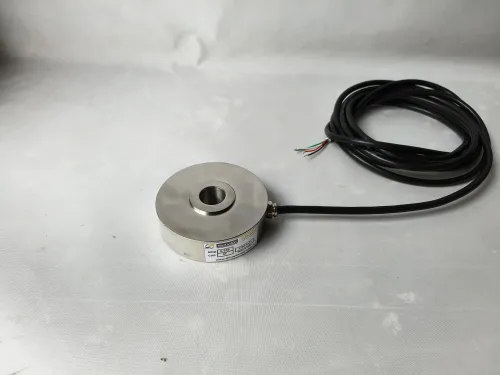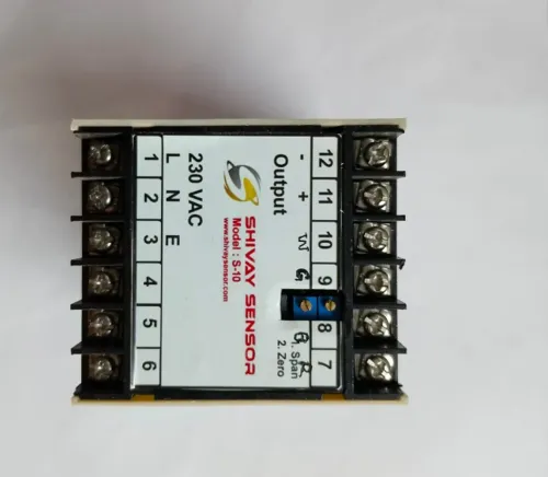
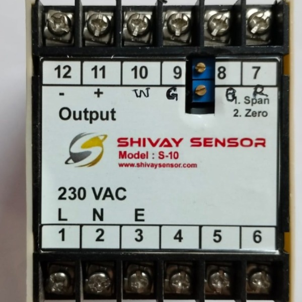
Precision Load Cell Signal Conditioners & Converters: The Complete Engineering Guide
In precision weighing, automated test stands, and industrial process control, the accuracy of your measurement system depends entirely on how clean your sensor signal remains between the transducer and the controller.
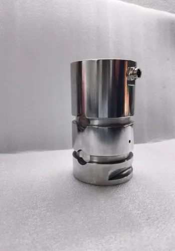
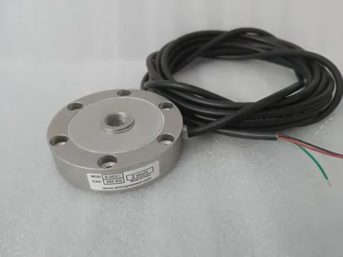
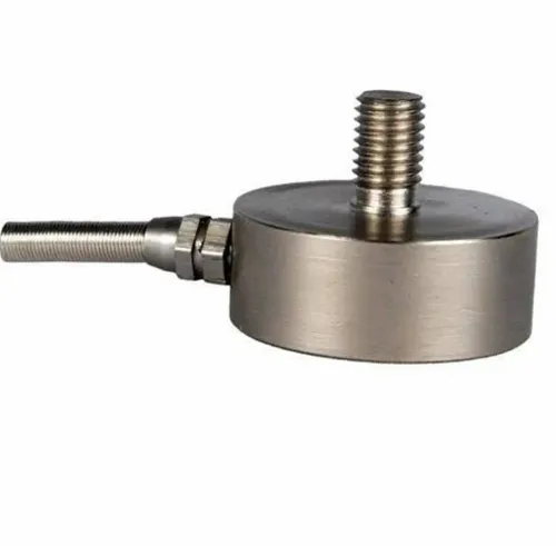
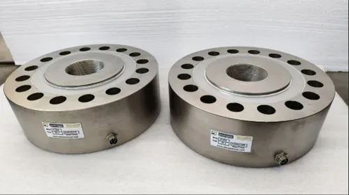
A strain gauge load cell produces an exceptionally small electrical output—typically in the millivolt range. Without specialized processing, this raw signal is vulnerable to electromagnetic interference (EMI), line resistance losses, and ambient thermal drift.
A precision load cell signal conditioner and converter bridges the gap between mechanical force and readable data. It converts delicate millivolt signals into robust, standardized analog outputs or high-resolution digital streams suitable for PLCs, PACs, and SCADA systems.
What Does a Load Cell Signal Conditioner Actually Do?
At its core, a load cell signal conditioner performs five essential signal chain operations:
1. Ultra-Stable Excitation Voltage
Strain gauge bridge circuits are ratiometric devices. If the excitation voltage delivered to the Wheatstone bridge fluctuates by even 0.1%, your calibrated weight reading fluctuates by that same 0.1%. Precision conditioners provide regulated, low-noise DC excitation (commonly 5 V or 10 V) with built-in remote sensing to compensate for voltage drops across extended cable runs.
2. Low-Noise Differential Amplification
A standard 2 mV/V load cell powered at 10 V yields a full-scale output of just 20 mV. A resolution of 1 part in 10,000 means resolving 2 microvolts ($2 mutext{V}$). Precision signal conditioners utilize low-offset instrumentation amplifiers that deliver high Common-Mode Rejection Ratios (CMRR > 100 dB) to amplify the true differential signal while rejecting common-mode ground noise.
3. Active Filtering and Noise Rejection
Factory floors and test rigs are full of high-frequency switching noise from variable frequency drives (VFDs), contactors, and wireless gear. Signal conditioners use multi-pole, low-pass active filters (such as Butterworth or Bessel topologies) to eliminate mechanical vibration artifacts and prevent aliasing before signal conversion.
4. Galvanic Isolation
High-end conditioners feature 2-way or 3-way galvanic isolation (typically 1,500 V to 3,000 V RMS) between power, input, and output channels. This eliminates ground loops, which are the leading cause of zero-point offset wander in industrial installations.
5. Signal Conversion
Depending on your downstream control architecture, the unit formats the conditioned signal into either:
- Isolated Analog Output: Standard process signals like 4–20 mA, 0–20 mA, 0–10 V, or ±10 V.
- Digital Conversion: Integrated 24-bit delta-sigma ($DeltaSigma$) analog-to-digital converters (ADCs) transmitting over RS-485, Modbus RTU/TCP, CANopen, Profinet, or EtherCAT.
Analog vs. Digital Load Cell Converters: A Direct Comparison
Choosing between an analog amplifier and a digital signal converter depends on cable distance, update frequency, and whether calibration should live on the hardware unit or in the PLC code.
FeaturePrecision Analog ConditionerDigital Converter / TransmitterTypical Outputs4–20 mA (current loop), 0–10 V DCModbus-RTU, CANopen, Profinet, IO-LinkResolutionContinuous / Infinite (limited by noise floor)16-bit to 24-bit ($DeltaSigma$)Transmission Range4–20 mA: Up to 1,000 m; 0–10 V: < 15 mFieldbus-dependent (RS-485 up to 1,200 m)Noise SusceptibilityLow (current loop); Moderate (voltage)Immunity over digital bus runsCalibration MethodMulti-turn trim potentiometers or dip switchesSoftware/Push-button zero & span calibrationDiagnosticsBasic (wire-break detection on 4–20 mA)Advanced (open circuit, bridge imbalance, alarms)Best Suited ForStandalone machines, direct analog PLC cardsMulti-channel scales, SCADA networks, Industry 4.0
Key Specifications to Evaluate Before Purchasing
When reviewing datasheets, don't just look at input range and supply voltage. Focus on these precision specifications:
Temperature Coefficient of Span and Zero
Temperature shifts cause resistance variations in both the load cell and the conditioning circuit. Look for:
- Zero Drift: $le pm 0.005% text{FS}/^circtext{C}$
- Span Drift: $le pm 0.005% text{FS}/^circtext{C}$
Units with chopper-stabilized or auto-zero amplifiers maintain long-term baseline stability across wide temperature ranges (-10°C to +60°C).
Linearity Error
Non-linearity reflects the deviation of the output curve from an ideal straight line. For high-precision applications (such as parts-counting bench scales or torque calibration rigs), choose units with non-linearity within $le pm 0.01%$ of Full Scale.
Bandwidth and Sampling Rate
- Static Weighing (silos, batch hoppers): Slower sampling rates (5 Hz to 20 Hz) combined with steep filtering reject ambient environmental vibration.
- Dynamic Testing (web tension control, impact drop tests, dynamic checkweighers): High update rates (1,000 Hz to 10,000 Hz) with low phase lag are required to catch peak impulse loads.
4-Wire vs. 6-Wire Bridge Excitation Support
Standard 4-wire connections carry $+/-$ Excitation and $+/-$ Signal. However, cable resistance fluctuations due to ambient temperature shifts cause excitation drops over long distances. 6-wire conditioners add $+/-$ Sense lines that measure the exact voltage directly at the load cell bridge terminals and dynamically adjust drive levels to compensate.
Best Wiring and Installation Practices
A high-grade signal conditioner cannot overcome bad grounding or poor shielding. Follow these wiring practices:
- Use Twisted-Pair Shielded Cable: Run signal and excitation leads in individually shielded, twisted-pair cables (e.g., Belden 8723).
- Single-Point Grounding: Ground the cable shield at one end only—typically at the signal conditioner's chassis/earth terminal. Grounding both ends creates circulating ground loops.
- Physical Segregation: Maintain at least 200 mm (8 inches) of separation between low-level load cell signal wiring and high-voltage AC lines or motor leads. Cross power cables at $90^circ$ angles if intersections are unavoidable.
- Use DIN-Rail Mounting in Enclosures: Mount conditioners in sealed NEMA 4 / IP65 enclosures away from high-heat components like braking resistors or variable frequency drives.
Common Industrial Applications
- Vessel, Silo, and Tank Weighing: Summarizing multiple load cells via junction boxes and transmitting a calibrated 4–20 mA signal straight into DCS batch systems.
- Material Testing Machines (Tensile/Compression): Real-time digital force streaming into PC-based data acquisition (DAQ) software via USB, CANopen, or Ethernet.
- Automated Packaging and Checkweighing: Rapid inline weight verification requiring high-speed filtering to isolate product weight from conveyor belt motor vibration.
- Injection Molding & Web Tension Control: Monitoring continuous clamping force and film tension under harsh factory electrical environments.
Summary: Getting the Most Out of Your Sensor Chain
Your load cell is only as good as the electronics translating its output. By investing in a precision load cell signal conditioner or converter with low thermal drift, active galvanic isolation, and the right output configuration (analog current loop or industrial digital bus), you ensure reliable, repeatable force and weight measurements across your entire operation.
#LoadCell #SignalConditioner #IndustrialAutomation #ProcessControl #WeighingSystems #SensorTechnology #Instrumentation #PLC #DataAcquisition #ManufacturingEngineering #LoadCells #SignalConditioner #StrainGauge #SignalConverter #InstrumentationAmplifier #IndustrialAutomation #PLC #SCADA #ProcessAutomation #ControlSystems #IIoT #WeighingSolutions #ForceMeasurement #TestAndMeasurement #DAQ #PrecisionMeasurement #ElectricalEngineering #AutomationEngineering #InstrumentationEngineer #FactoryAutomation
Keywords